
Backflow preventer valve

a preventer valve and backflow technology, applied in the field of water delivery systems, can solve the problems of not being tamperproof, generally expensive to purchase, laborious installation, etc., and achieve the effects of preventing leakage, facilitating securing the valve, and convenient insertion

Inactive Publication Date: 2009-09-10
SIVAN VALVES
View PDF3 Cites 13 Cited by
  • Summary
  • Abstract
  • Description
  • Claims
  • Application Information

AI Technical Summary

Benefits of technology

[0014]An insertable backflow preventer is presented. The backflow preventer is provided with a cylindrical housing, and can be easily inserted into any standard size NPS pipe or copper tube. The apparatus can also have an external flange at one end to secure its position when inserted into the exposed end of a pipe or tube, as the flange insures that the check valve can never be inserted backwards. The housing can have a flow transition zone, a proximal orifice / ball seat—the seat optionally having an “O” ring, retaining channel (groove) therein, or alternatively, a coated surface to prevent leakage when the check ball is forced into the orifice / ball seat when the backflow preventer valve is subjected to low differential pressures during a backflow condition—a ball with a specific weight that is a function of that of the surrounding fluid, and a distal retaining screen. The housing can have a flange provided on the outside of the housing at one end to facilitate securing the valve in a pipe. The valve can be self-cleaning, can be placed in any orientation in a pipe and has low hydraulic head-loss. The valve's unique cost-effective design provides for easy and relative quick installation, eliminates the need to reconfigure existing plumbing, and can be performance tested remotely. Properly installed, it can dramatically improve the security of, for example, potable water sources in a building or other context, and inasmuch as when installed it is not visible, it is tamper proof. The valve can be scaled to any size pipe or tube. Multiple valves can be installed in series, and balls of varying specific weights can be used in each valve in such series to allow for contexts where a range of fluids are sent through the same line, or to provide fail-safe operation in the event that contaminants change the specific gravity of the fluid. The housing can have a fluid inlet, a main flow conduit and a fluid outlet. The caged ball can move freely within the internal space between the distal retaining screen and the proximal orifice / seat, essentially longitudinally. The movement and position of the ball within the valve is governed by the direction and rate of flow of the fluid surrounding the ball. In exemplary embodiments of the present invention the ball and internal structures of the entire apparatus can be made smooth so as to minimize fluid head-loss, insure that the caged suspended ball can move freely therein, seat correctly in the valve orifice / seat, and instantly respond to changes in fluid pressure, whether large or small, and direction.

Problems solved by technology

As such they are not tamper resistant or tamperproof.
They are generally costly to purchase and, always labor intensive to install.
Left unchecked, hydraulic reversal can compromise the quality and safety of a building's potable water supply system and, potentially, the municipal water supply distribution system as well.
This leaves such buildings' internal potable drinking water supply vulnerable to compromise via injection of a toxic chemical or biological contaminant into the building's water supply system, with the added possibility of contaminating the municipal water supply distribution system in the process.
The latter could compromise the water quality of an entire regional water distribution grid.
While municipal codes generally require the replacement of single check valves with a double check valve backflow preventer, simply requiring building owners to undertake major re-plumbing to install these backflow preventers between the municipal water service distribution lines located in the street and downstream of the building's water meter would not address the vulnerability to intentional internal contamination within a given building.
Retrofitting a conventional backflow preventer to protect a building's internal potable water distribution system from possible intentional contamination at every point-of-use water supply terminus, such as, for example, via shutoff valves for kitchen and bathroom fixtures, drinking water fountains, etc., could be very expensive.
Moreover, access for repair and replacement must be provided for each such back flow preventer to provide for proper maintenance, since these devices are generally internally mechanically complex.
Even in new construction, installation of conventional back flow preventers for each point-of-use fixture would be costly.
As noted in a Jun. 18, 2004 article entitled “Cross Connection Control Programs And Backflow Preventers Are Essential Components of Safe Drinking Water Systems,” published on Backflow Prevention TechZone (a trade web site at URL http: / / www. backflowpreventiontechzone followed by .com), plumbing system cross connections between potable and non-potable water supplies, water using equipment, and drainage systems, continue to be a serious potential public health hazard worldwide.
Anywhere people congregate and utilize communal water supplies, water using equipment, and drainage systems, the danger of un-protected cross connections continue to threaten public health.
The report further noted that backflow preventer device development, beyond simple check valves, began to accelerate and diversify in the mid-20th century, but potable (“city”) water piping systems and water using equipment, especially inside industrial and medical buildings, have grown exponentially in complexity and are also continuously altered.
The predominant cause for the cross connection, known as backsiphonage, is the sudden and significant loss of hydraulic pressure in the water main.
Buildings near a municipal water main break or a fire hydrant being opened will experience a lowering of the water pressure and possibly backsiphonage.
Such devices are external in their intended application, limited to a specific installation orientation, e.g., vertical or horizontal, visible, must be easily accessible and are thus vulnerable to tampering, are mechanically complex to the extent that periodic inspections and maintenance are required and without proper servicing are unreliable in the long term, and are operationally affected by gravity in whole or part.
In addition, all conventional backflow preventers, because of their inherent design, are prone to clogging and fouling.
Such mechanical complexity actually fosters corrosion, clogging and / or fouling, and thus are unsuitable to resolve in a cost-effective manner the aforementioned public drinking water supply safety concerns.
Additionally, conventional backflow valves require a great deal of effort in both labor and material to be installed, and as a result of their design must always be readily accessible, i.e., exposed, to provide for required periodic maintenance.

Method used


Image

  • Backflow preventer valve
  • Backflow preventer valve
  • Backflow preventer valve

Examples


Embodiment Construction

[0053]The present invention will be described with reference to various exemplary embodiments. It should be understood that none of such descriptions are limiting, and all descriptions of exemplary embodiments and their respective components are exemplary, and for illustrative purposes. The present invention is understood to be capable of implementation in various other embodiments and variations of embodiments than those described herein, as will be understood by those skilled in the art.

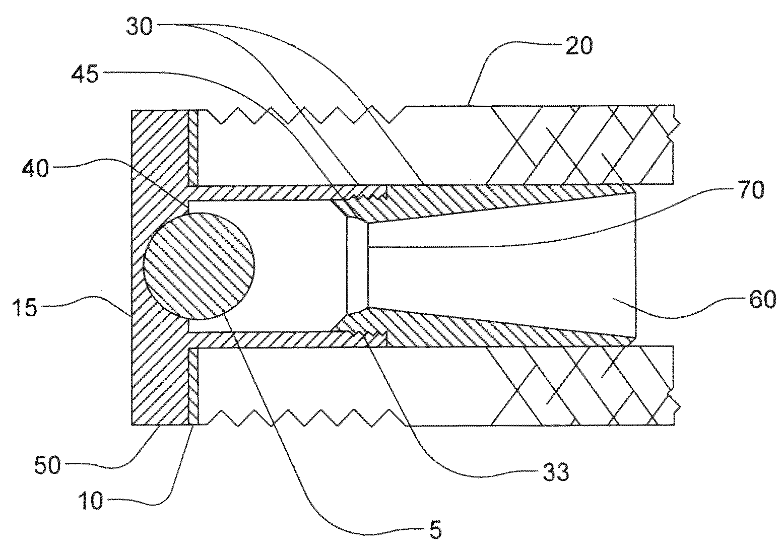
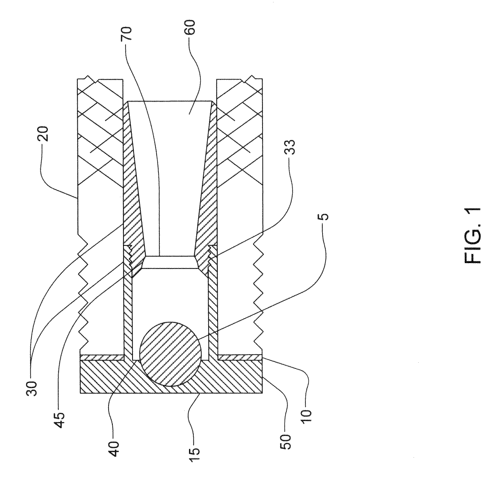
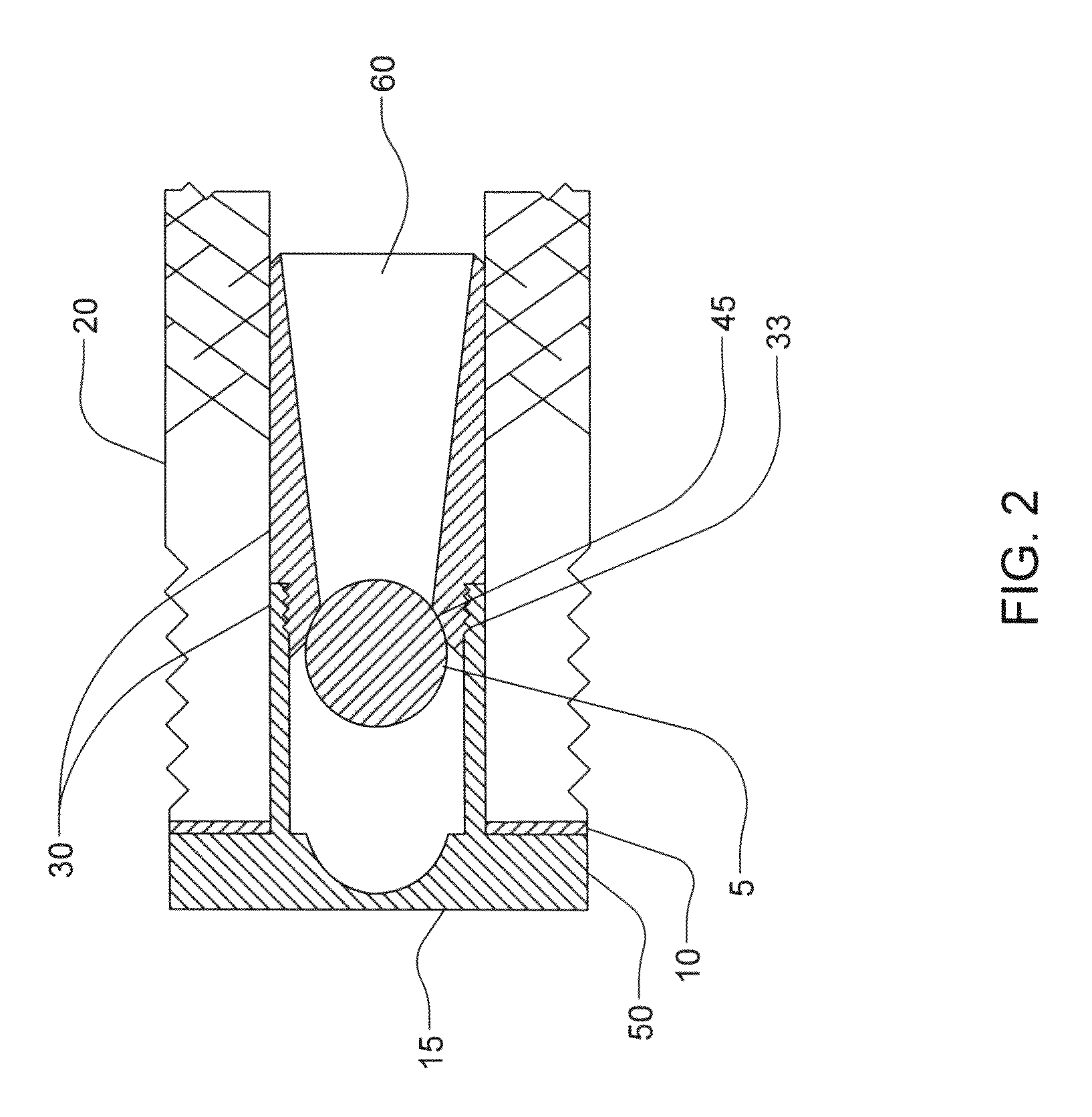
[0054]In exemplary embodiments of the present invention, an insertable backflow preventer valve (hereinafter sometimes referred to as a “BFP”) can have a ball, and a valve housing. The housing can be provided in two parts, which can, for example, be screwed together to hold the ball there between. The housing can have, for example, a retaining screen on its front end (the distal, or outflow side) and a sealable orifice at its rear end (the proximal, or inflow side). The retaining screen can be prov...


PUM


Abstract

An insertable backflow preventer is presented. The backflow preventer is provided with a cylindrical housing. The housing has a flow transition zone, a proximal orifice / ball seat, a ball with a specific weight that equals or is close to the specific weight of the surrounding fluid, and a distal retaining screen. The housing can have a flange provided on the outside of the housing at one end to facilitate securing the valve in a pipe. The valve is self-cleaning, can be placed in any orientation in a pipe and has low hydraulic head-loss. The valve's unique cost-effective design provides for easy and relative quick installation, eliminates the need to reconfigure existing plumbing, and can be performance tested remotely. Properly installed, it can dramatically improve the security of, for example, potable water sources in a building or other context, and inasmuch as when installed it is not visible, it is tamper proof. The valve can be scaled to any size pipe or tube, and due to its internal flow dynamics is self cleaning. Multiple valves can be installed in series, and balls of varying specific weight can be used in each valve in such a series to allow for contexts where a range of fluids are sent through the same line, or to provide fail-safe operation in the event that contaminants change the specific gravity of the fluid.

Description

CROSS REFERENCE TO RELATED APPLICATIONS[0001]This application claims the benefit of U.S. Provisional Patent Application Ser. Nos. 60 / 811,676, filed on Jun. 6, 2006; 60 / 847,242, filed on Sep. 26, 2006; and 60 / 905,386, filed on Mar. 6, 2007.[0002]Continuation-in-part of application Ser. No. 11 / 810,946, filed on Jun. 6, 2007.TECHNICAL FIELD[0003]The present invention relates to water delivery systems, and in particular to a backflow preventer valve for use to increase the security of, and prevent tampering with, water supplies.BACKGROUND OF THE INVENTION[0004]Backflow preventers are used to prevent contamination of a building and / or public water distribution system by reducing or eliminating backflow of a contaminated hazardous fluid into the respective system(s). Conventional backflow preventers are mechanically sophisticated devices, that are threaded for pipes, unthreaded for tubing, or flanged at each end so they can be installed, i.e., spliced into the piping system. Conventional ...

Claims


Application Information

Patent Timeline
IPC IPC(8): F16K15/00
CPCE03B9/16F16K15/048F16K15/04E03C1/104Y10T137/7873
Inventor MONTAGUE, ALBERT
Owner SIVAN VALVES
Learn More