
Measurement of liquid flow in porous media by tracer dilution without continuous mixing

a tracer dilution and liquid flow technology, applied in the direction of fluid speed measurement, instruments, construction, etc., can solve the problems of increasing resistance to lnapl flow, difficult handling of petroleum liquids, and accumulation of such liquids beneath

Active Publication Date: 2009-09-10
CHEVROU USA INC +1
View PDF5 Cites 4 Cited by
  • Summary
  • Abstract
  • Description
  • Claims
  • Application Information

AI Technical Summary

Benefits of technology

[0006]Accordingly, an advantage of the present invention is to provide an apparatus and method for measuring fluid flow in porous media without requiring sustained in-well mixing over extended time periods.

Problems solved by technology

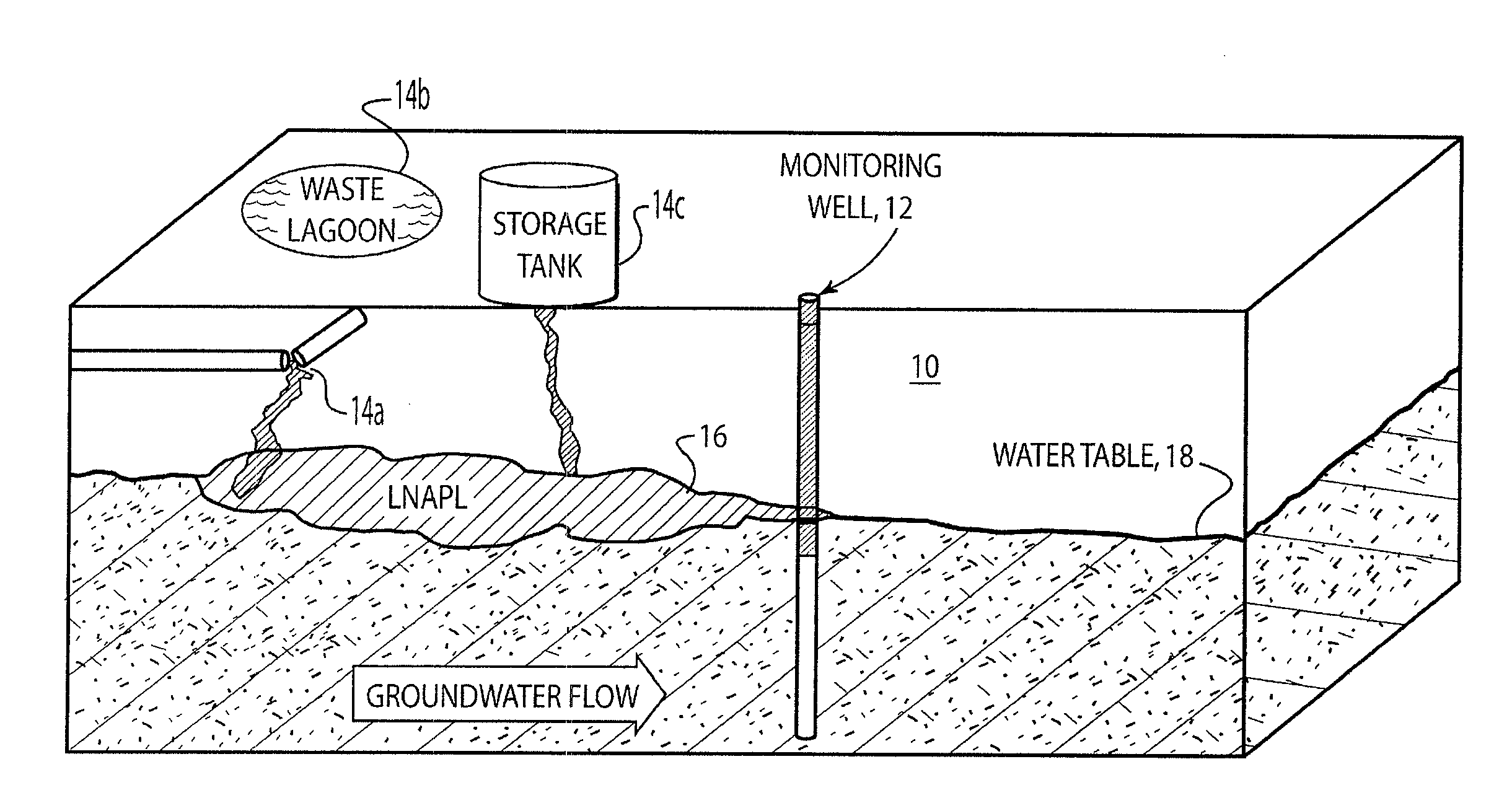
Handling of petroleum liquids can be challenging, sometimes resulting in accumulation of such liquids beneath petroleum production, transmission, refining, and storage facilities.
While active releases of LNAPL often expand, once the LNAPL release ceases, resistance to LNAPL flow increases due to LNAPL depletion associated with dissolution and volatilization.
Furthermore, forces driving LNAPL migration diminish as LNAPL concentrations in release areas decay.

Method used


Image

  • Measurement of liquid flow in porous media by tracer dilution without continuous mixing
  • Measurement of liquid flow in porous media by tracer dilution without continuous mixing
  • Measurement of liquid flow in porous media by tracer dilution without continuous mixing

Examples


example 1

Laboratory Experiments

[0042]Single-well, non-continuous mixing tracer dilution tests were conducted in a sand tank, a schematic representation of a side view thereof being illustrated in FIG. 7, in order to investigate the correspondence between measured LNAPL flow rates using non-continuous mixing tracer dilution with imposed LNAPL flow rates over a range of LNAPL thicknesses and LNAPL flow rates. The sand tank is described in more detail in Taylor, supra, and in Sale et al., supra, and is filled with Unium 4095, a well-sorted, medium-grained, angular quartz sand. Tests were conducted using center well 12 which contains a vertical half-section of a 2-in. inner diameter, 0.030 in. slot, wire wrap stainless steel well screen. The open section of the screen faces the glass in the tank, and a 1-in. filter pack consisting of well-sorted, coarse-grained, angular quartz sand (Unium 2095) was placed around the well screen. Initially, the tank was fully filled with tap water. Subsequently, ...

example 2

Field Experiments

[0049]A first set of measurements involved determining LNAPL fluxes through monitoring wells adjacent to active LNAPL recovery wells to evaluate whether LNAPL fluxes at the wells agreed with LNAPL fluxes at the production wells. A second set of experiments involved measuring LNAPL flow rates in monitoring wells in areas where LNAPL bodies are thought to be largely stable for providing a basis for estimating the minimum LNAPL fluxes that can be measured. Sediments in the intervals where LNAPL is observed consist of fine to medium quartz feldspar sand. The two active recovery wells (R-93, 40, and R-91, 42) employed in the study and associated 2-inch monitoring wells are illustrated in FIGS. 10A and 10B, respectively. The thickness of LNAPL in monitoring wells TW-416, 44, TW-418, 46, TW419, 48, and TW420, 50, were 0.61 ft, 0.65 ft, 0.28 ft, and 0.57 ft, respectively. These wells include 30-slot PVC well screens and coarse gravel packs. Based on monthly data, recovery r...

example 3

Field Experiments Using Water

[0053]The non-continuous mixing tracer dilution method of the present invention was used to measure rates of groundwater flow at five wells completed in an alluvial aquifer. Fluorescein was used as the water soluble tracer at an approximate concentration of 10 mg / L. Due to the small size of the wells (1-inch I.D.), in-well standards could not be placed in each the wells. Alternatively, a single well with no tracer was used as the zero concentration in-well standard. A second well, equipped with a small pipe, closed at the bottom and filled with formation water in which fluorescein was dissolved, was used as the 100% concentration in-well standard. Tracer concentrations were measured 5 times over a period of approximately 24 h. Prior to each measurement, tracer and water in the wells was remixed to achieve a uniform distribution of tracer in the water, in the wells. Changes in tracer concentrations between mixing events were used to estimate groundwater v...


PUM


Abstract

A natural gradient, single well, tracer dilution non-continuous mixing apparatus and method for measuring flow of liquids through porous media are described. The method has been applied to concentrations of Light Nonaqueous Phase Liquid (LNAPL) in monitoring wells to measure the rate of LNAPL flow through the wells and through the adjacent formation. Similar measurements were made for concentrations of water in other formations. A LNAPL-soluble fluorescing tracer was added to LNAPL in the wells, and a water-soluble fluorescing tracer was added to water in the wells. The tracer is initially uniformly-mixed into the LNAPL or water in the well, and the tracer concentration is measured using a fiber optic cable and a spectrometer. The LNAPL or water with dissolved tracer is then allowed to flow from the well without any mixing. At a later time, the LNAPL or water and tracer in the well are mixed to a uniform tracer concentration, and the tracer concentration is remeasured. Using the initial tracer concentration, the subsequently mixed tracer concentration, the elapsed time, and the well diameter, a LNAPL flow rate is calculated.

Description

RELATED CASES[0001]The present application claims the benefit of provisional patent application Ser. No. 61 / 034,475 for “Resolution Of Fluid Stability Using Tracers” by Timothy J. Smith et al., filed on 6 Mar. 2008, which provisional application is hereby incorporated by reference herein for all that it discloses and teaches.FIELD OF THE INVENTION[0002]The present invention relates generally to measurement of liquid flow through porous media and, more particularly, to the use of tracer dilution for measuring liquid flow through porous media.BACKGROUND OF THE INVENTION[0003]Handling of petroleum liquids can be challenging, sometimes resulting in accumulation of such liquids beneath petroleum production, transmission, refining, and storage facilities. Petroleum liquids in subsurface environments are referred to as Light Non-Aqueous Phase Liquids (LNAPLs). LNAPLs may impact groundwater quality and indoor air quality, and may migrate into unimpacted soils and / or surface water bodies.[00...

Claims


Application Information

Patent Timeline
IPC IPC(8): G01F1/708
CPCB09C1/00G01F1/704E21B47/1015E21B47/11
Inventor SALE, THOMAS C.SMITH, TIMOTHY J.LYVERSE, MARK
Owner CHEVROU USA INC
Learn More