Eureka AIR delivers breakthrough ideas for toughest innovation challenges, trusted by R&D personnel around the world.

Tilting Flatbed Trailer for Loading, Transporting, Unloading and Placement of Heavy Field Equipment

a technology for trailers and heavy equipment, applied in the direction of loading/unloading vehicle arrangment, transportation items, refuse collection, etc., can solve the problems of complex technology, schedules and operations, and equipment types that cannot meet the unique needs of the oil and gas industry, and achieve the effect of drastically reducing the likelihood of damag

Inactive Publication Date: 2009-09-03
BERNEY JASON EUGENE +2
View PDF17 Cites 13 Cited by
  • Summary
  • Abstract
  • Description
  • Claims
  • Application Information

AI Technical Summary

Benefits of technology

[0013]At no time during the loading and unloading operation is any equipment dropped or dragged to or from the trailer system. The likelihood of damage is drastically reduced. Additionally, because of the maneuverability and compact design, equipment can be placed in its exact operational location.

Problems solved by technology

Today's oil and gas development operations are a complex matrix of technologies, schedules and operations.
This equipment type is extremely expensive and heavy.
Conventional heavy trailer equipment and existing designs do not meet the unique needs of the oil and gas industry with regard to large water pumps and similar equipment.
Though hard to believe, large expensive equipment delivered to field operational sites is often dragged off of and dropped from traditional heavy equipment trailers.
Damage to the equipment is routine and the delay in waiting for repairs is also costly.
Fork lifts and cranes are routinely rented for the sole purpose of picking up and placing this heavy equipment onto traditional trailers; again wasting time and resources.
Additionally, traditional trailer equipment, due to its size and weight, often cannot even come onto a drill site under wet or soft soil conditions, further limiting it's usefulness.
Furthermore, traditional equipment cannot accurately place this heavy equipment at the exact location preferred for operation.

Method used


Image

  • Tilting Flatbed Trailer for Loading, Transporting, Unloading and Placement of Heavy Field Equipment
  • Tilting Flatbed Trailer for Loading, Transporting, Unloading and Placement of Heavy Field Equipment
  • Tilting Flatbed Trailer for Loading, Transporting, Unloading and Placement of Heavy Field Equipment

Examples


Embodiment Construction

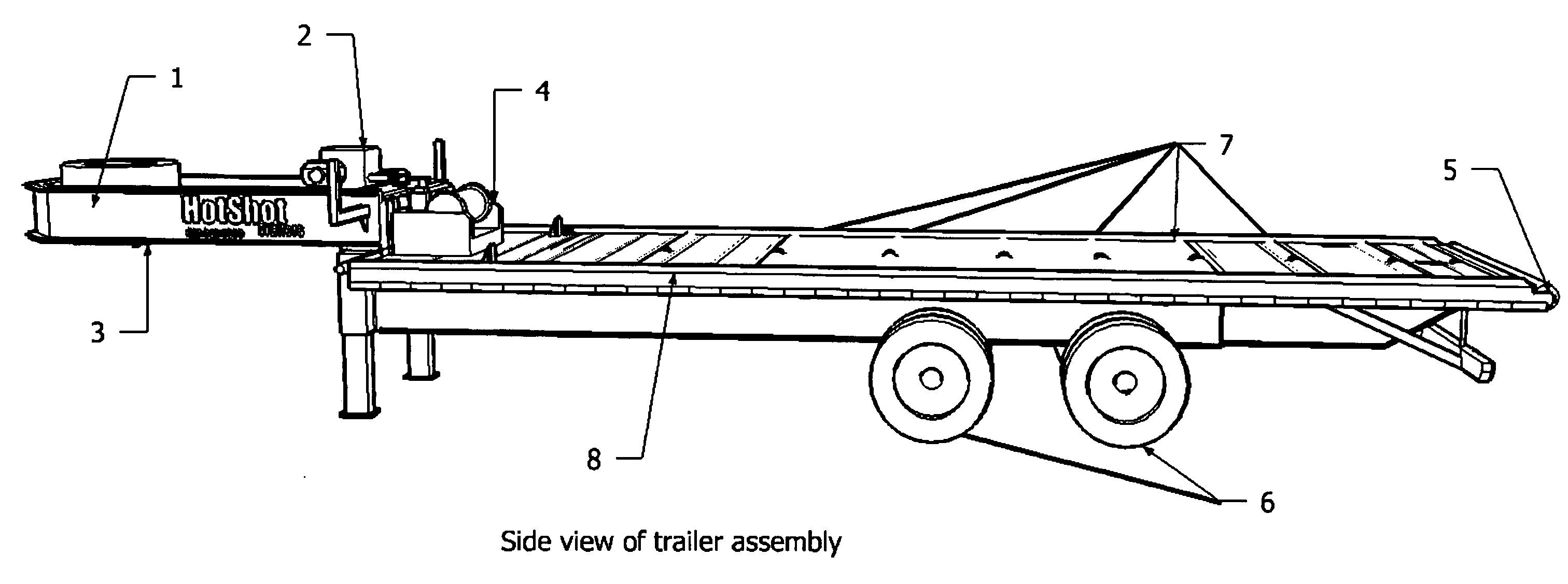
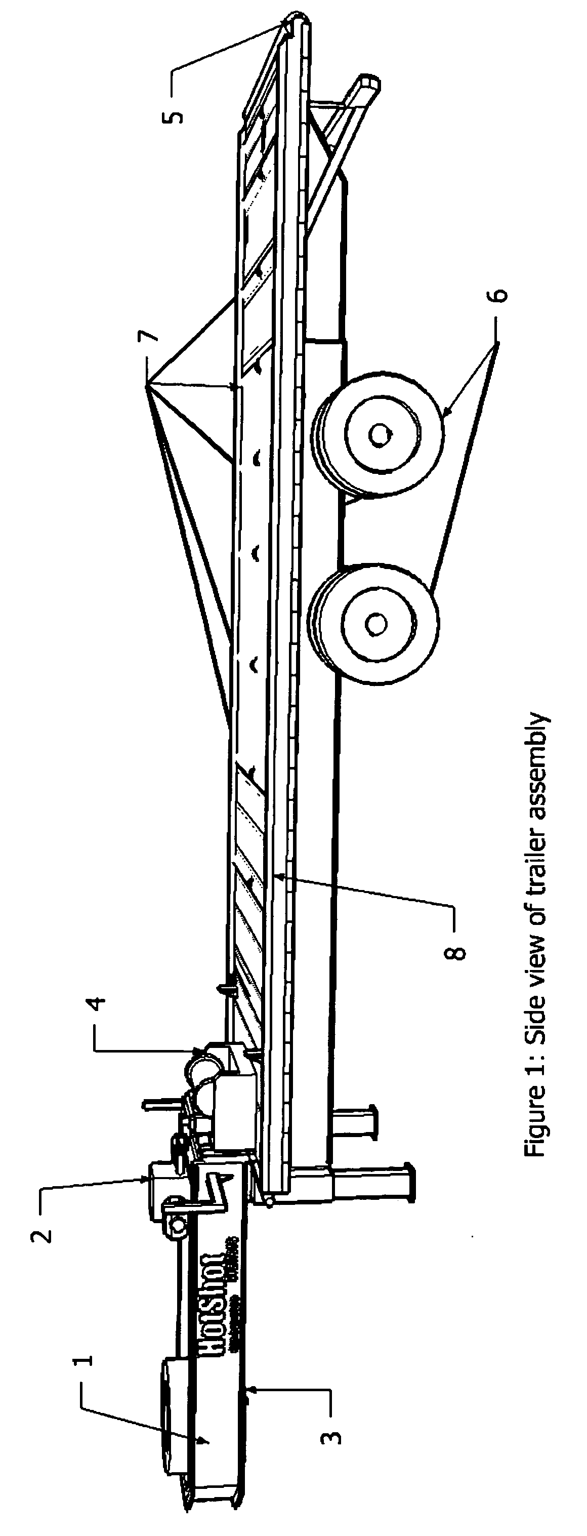
[0025]100. The disclosed invention utilizes a goose-neck flatbed trailer 1 configuration as a base. The trailer can be pulled using commercially available 5th wheel hitch 3 assemblies. The present embodiment utilizes a dual tandem axle set 6 and heavy duty spring suspension set.

[0026]101. The flatbed portion of the trailer 8 further encompasses a hydraulic tilt system 9 in which the front edge of the trailer bed surface can be raised to an angle sufficient to cause the rear edge of the trailer to rest at or near ground level. A dual hydraulic cylinder 9 raises the forward end of the flatbed base. The trailer bed consists of a double beam design 12 in which the inside beam structure is raised by the hydraulic cylinders. The trailer bed and interior beam structure pivots at a point near and above the rear axle of the trailer 13. The pivot point is accomplished by means of a 2 inch diameter solid steal rod which extends through both interior and exterior beam structures.

[0027]102. This...


PUM


Abstract

A system and a method for loading, transporting and unloading large, heavy field equipment to and from nontraditional operational location. The invention discloses a specially designed tilt flatbed trailer, a winch and cabling mounted near the front of the trailer bed, and heavy duty steel rollers imbedded into the flatbed surface. Initially, the trailer is positioned in an upwardly titled angle such that the rear edge of the trailer bed is near ground level next to the lead edge of the equipment. The winch cabling is attached to the equipment and pulls it over the rear edge of the trailer via a larger receiving roller. The equipment is pulled upward and onto the trailer bed until the rear edge of the equipment base clears the ground. The tilt bed is then lowered to a horizontal position. During loading, the equipment moves smoothly onto the trailer surface via the embedded rollers. To unload, the process is reversed.

Description

CROSS-REFERENCE TO RELATED APPLICATIONS[0001]Not ApplicableSTATEMENT REGARDING FEDERALLY SPONSORED RESEARCH OR DEVELOPMENT[0002]Not ApplicableREFERENCE TO SEQUENCE LISTING, A TABLE, OR A COMPUTER PROGRAM LISTING COMPACT DISC APPENDIX[0003]Not ApplicableBACKGROUND OF THE INVENTION[0004]Although the oil and gas industry has been flourishing and developing for over one hundred and fifty years, innovation and efficiency are still in high demand. Today's oil and gas development operations are a complex matrix of technologies, schedules and operations. Large amounts of capital, both manpower and money, are on-the-line in the attempt to produce valuable oil, gas or both from a well.[0005]Various types of equipment are used during the drilling and production process. Water is an essential resource for mixing drilling mud, cooling equipment and for secondary recovery efforts from existing wells. Large water pumps and similar equipment are routinely dispatched and used for these operations. T...

Claims


Application Information

Patent Timeline
IPC IPC(8): B60P1/22
CPCB60P1/6454B60P1/52
Inventor BERNEY, JASON EUGENEBERNEY, DEBRABERNEY, HARRY
Owner BERNEY JASON EUGENE
Why Eureka
Eureka Blog
Learn More