High speed orbiting ball media processors

Inactive Publication Date: 2009-09-03
UNIV OF FLORIDA RES FOUNDATION INC
View PDF6 Cites 1 Cited by
  • Summary
  • Abstract
  • Description
  • Claims
  • Application Information

AI Technical Summary

Problems solved by technology

The vibratory motion of the milling tube within these prior art ball mills typically causes the milling balls to move in a generally chaotic manner within the milling tube and / or to move from one end of the milling tube to the other while the ball mill is in operation.
In addition, prior art ball mills often take a relatively long time (commonly several hours) to transform target particles into flakes.
Furthermore, these prior art ball mills are not able to produce flakes with certain desired properties.

Method used


Image

  • High speed orbiting ball media processors
  • High speed orbiting ball media processors
  • High speed orbiting ball media processors

Examples


Embodiment Construction

[0023]The present inventions now will be described more fully hereinafter with reference to the accompanying drawings, in which some, but not all embodiments of the inventions are shown. Indeed, these inventions may be embodied in many different forms and should not be construed as limited to the embodiments set forth herein. Rather, these embodiments are provided so that this disclosure will satisfy applicable legal requirements. Like numbers refer to like elements throughout.

Single Batch Milling Machine

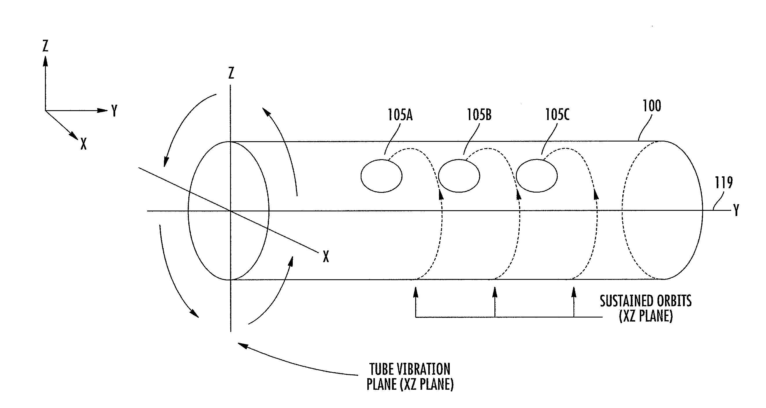
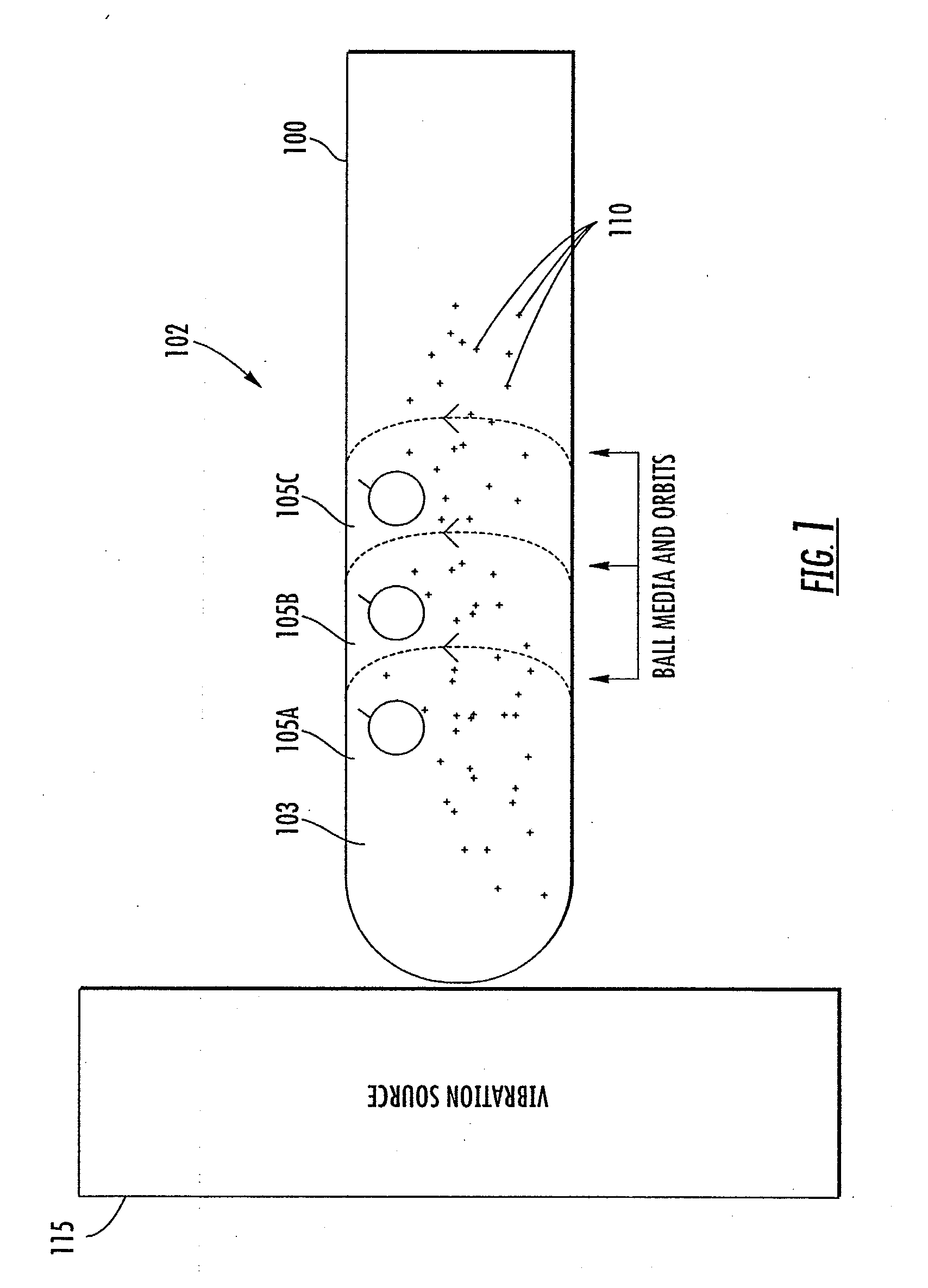
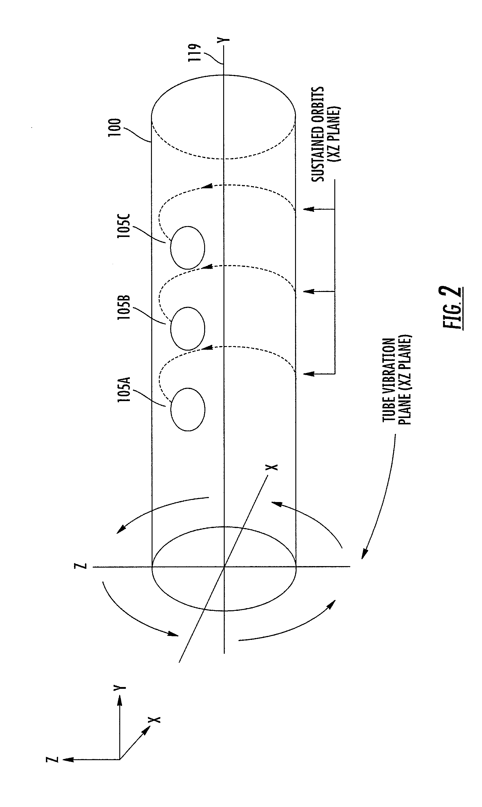
[0024]FIG. 1 depicts a single batch milling machine 102 according to a particular embodiment of the invention. As may be understood from this figure, in this embodiment, the milling machine 102 includes a substantially cylindrical milling tube 100 that defines a substantially cylindrical interior portion 103. The milling tube is dimensioned to house one or more (and preferably a plurality of) milling balls 105A-105C and target particles 110 to be processed by the milling machine 102...


PUM


Abstract

According to one embodiment, a ball mill for working generally spherically shaped target particles into a flake-shaped end product is provided. The ball mill includes a milling tube, one or more milling balls disposed within the milling tube, and a vibration source that is positioned and adapted to move the milling tube such that its central axis follows along a substantially circular path. The continuously changing direction of the acceleration of the milling tube results in each of the milling balls following a respective, substantially orbital path about the milling tube's central axis. As the milling balls follow the respective, orbital paths, the milling balls come into contact with and transform the target particles into flakes. In a further embodiment, the ball mill may further include a virtual particle separator configured to route intermediate particles back to an inlet portion of the milling tube for additional processing time.

Description

BACKGROUND OF THE INVENTION[0001]Ball mills are currently used to work generally spherical target particles (e.g., metal particles) into an end product that is generally in the form of a flake (i.e., a particle that has a high diameter-to-thickness aspect ratio). The basic operation of exemplary prior art ball mills is described in U.S. Pat. No. 4,115,107 to Booz.[0002]As may be understood from the Booz patent, such prior art ball mills include a cylindrical milling tube, a vibration mechanism for oscillating the tube longitudinally back and forth along the milling tube's central axis (i.e., the milling tube's axis of symmetry), and a plurality of milling balls that are used to grind target particles into the desired form. The vibratory motion of the milling tube within these prior art ball mills typically causes the milling balls to move in a generally chaotic manner within the milling tube and / or to move from one end of the milling tube to the other while the ball mill is in opera...

Claims


Application Information

Patent Timeline
IPC IPC(8): B02C17/04
CPCB02C17/14
Inventor WU, CHANG-YUJEON, KI-JOONTHEODORE, ALEXANDROS D.
Owner UNIV OF FLORIDA RES FOUNDATION INC
Why Eureka
Try Eureka