
Method and system for controlling an internal combustion engine

a technology of internal combustion engine and expansion ratio, which is applied in the direction of electrical control, process and machine control, etc., can solve the problems of increased expansion ratio of internal combustion engine in order to further improve operating efficiency and output, abnormal combustion, and decreased possibility of abnormal combustion in the operation range with higher engine speed than the above-described low engine speed range, so as to improve engine operating efficiency and improve emission characteristics , the effect of reducing the amount of cylinder air charg

Active Publication Date: 2009-08-27
MAZDA MOTOR CORP
View PDF11 Cites 20 Cited by
  • Summary
  • Abstract
  • Description
  • Claims
  • Application Information

AI Technical Summary

Benefits of technology

[0002]Recently, in order to improve emission characteristics etc., controlling opening and / or closing timing for an intake valve of an internal combustion engine according to operation conditions has been developed. One example of a method of operating an opening / closing timing for intake and exhaust valves is described by U.S. Pat. No. 6,626,164 B2. The method described in this reference closes an intake valve later during a cylinder cycle than a bottom dead center when an engine operates in medium-load range. On the other hand, when the engine operates in a full-load range, the method closes an intake valve earlier during a cylinder cycle than in a middle-load range. That is, the cylinder air charge amount is decreased by retarding a closing point of an intake valve as engine load is smaller. As a result, by using this method, a need for controlling an amount of inducted air will decrease, thereby pump loss accompanying pressure drop in an intake passage will decrease, and therefore pressure drop in a cylinder in an intake stroke is suppressed, which results in improved engine operating efficiency.
[0003]The method described in this reference also retards an opening timing for an intake valve as an engine speed increases within a range in which there is substantially no induced air blowing back through an inlet of a cylinder in an opposite direction when an engine operates in a full-load region.

Problems solved by technology

However, increasing an expansion ratio of an internal combustion engine in order to further improve operating efficiency and output is difficult to achieve due to the following issues.
When a geometric compression ratio of an internal combustion engine is high, if a cylinder air charge filling ratio is in a high range under a low engine speed condition (a condition where a number of rotations is in low range and gas-flow rate in a cylinder is in low range), an air-fuel mixture in the cylinder is over-heated in a compression stroke resulting in abnormal combustion.
In the abnormal combustion, a phenomenon can occur, in which unburned air-fuel mixture is auto-ignited before spark ignition, or an unburned part of air-fuel mixture in the cylinder is over-compressed and auto-ignited after spark ignition due to excessive temperatures before flame propagation.
Further, a possibility of abnormal combustion in an operation range with higher engine speed than the above-described low engine speed range is decreased.
Further, a possibility of abnormal combustion in an operation range with higher engine speed than the above-described low engine-speed range is decreased.
Typically, in an internal combustion engine with a higher geometric compression ratio, in-cylinder temperature can be easily increased by compressing action and thus, there is a high possibility of abnormal combustion.

Method used


Image

  • Method and system for controlling an internal combustion engine
  • Method and system for controlling an internal combustion engine
  • Method and system for controlling an internal combustion engine

Examples


second embodiment

[0085]Further, specific values of the closing timing IVC of the intake valve 21, the reference air charge amount, the engine speed N1, N2 and N3, and the like are not limited to those described above. Next, the invention is described with reference to the drawings.

[0086]In the second embodiment, in addition to the control of the closing timing of the intake valve 21 in the above described embodiment, the opening timing of the intake valve 21 and the closing timing of the exhaust valve 22 are controlled. An outline of the second embodiment is such that when the target air charge amount CED is the maximum and the engine speed NENG is N5 or less, the opening timing of the intake valve 21 is controlled to be advanced, and the closing timing of the exhaust valve 22 in the cylinder 11 is controlled to be retarded as the engine speed NENG increases. Further, when the engine speed NENG is smaller than a predetermined speed N4 or less which is smaller than N5, the exhaust valve 22 is control...

third embodiment

[0116]Furthermore, the intake valve 21 and the exhaust valve 22 may be controlled to have no negative overlap period at the full load condition over the entire engine speed range. Such control is applied on a third embodiment that will be described now.

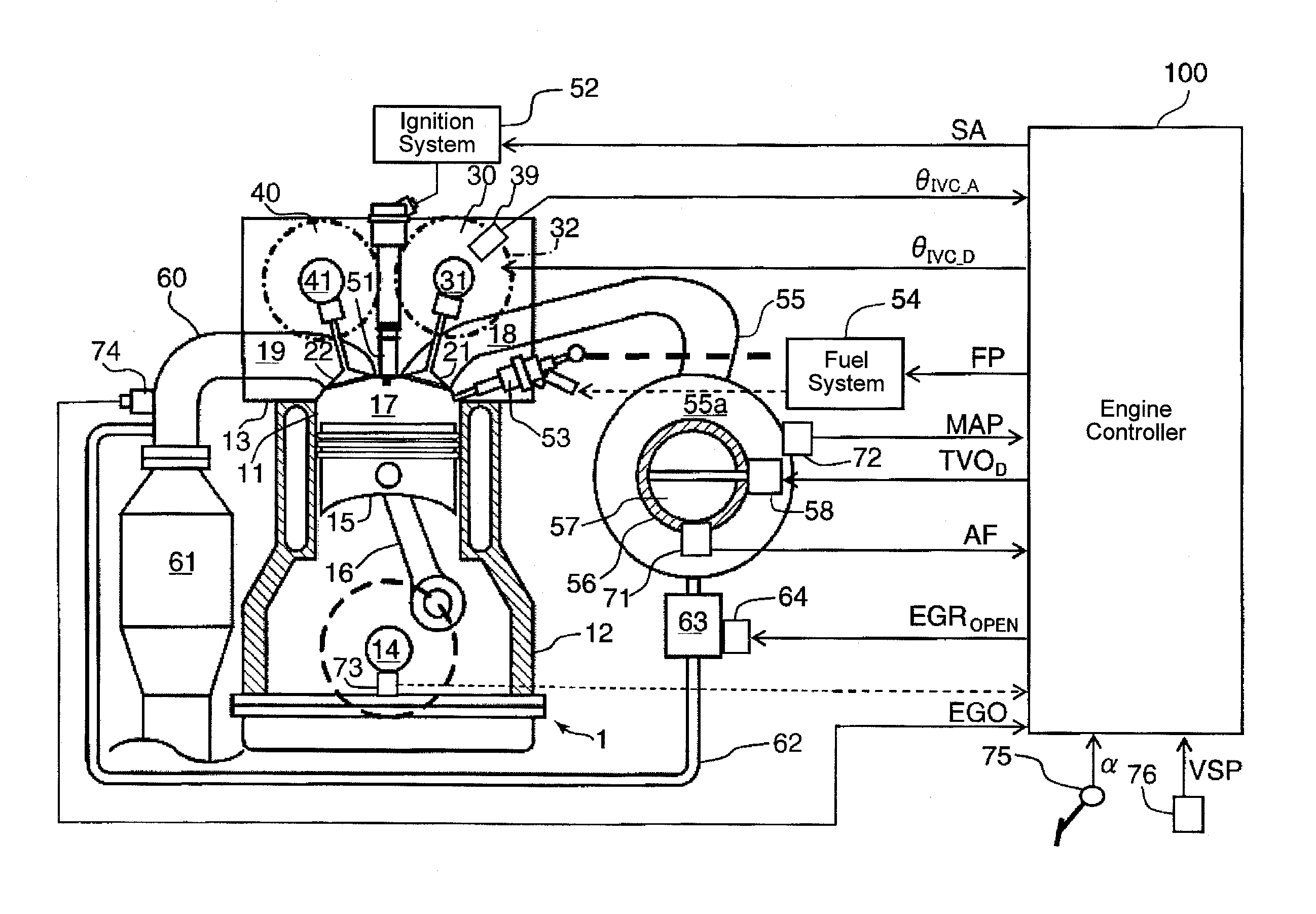
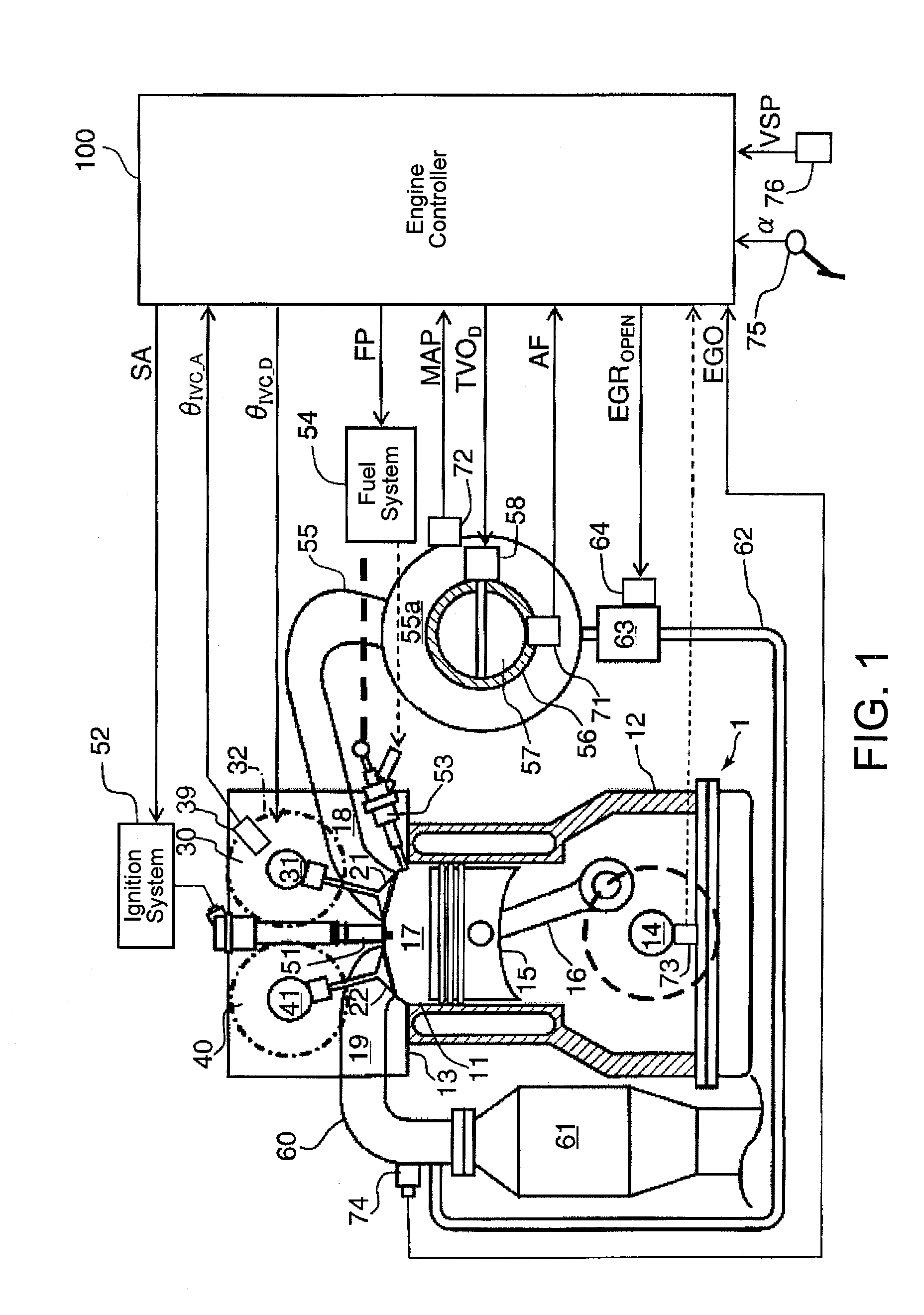
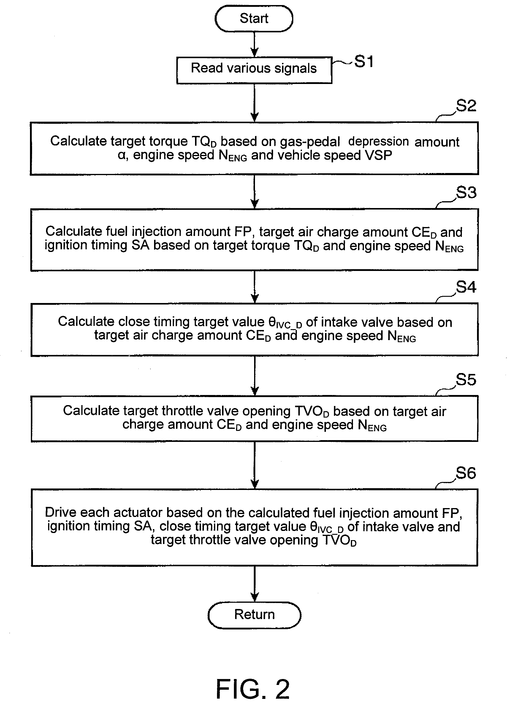
[0117]The third embodiment has the engine system described above with reference to FIG. 1. The control procedure executed by the engine controller 100 is same as described above in terms of the second embodiment with reference to the flowchart in FIG. 8.

[0118]The engine controller 100 controls angular phases of the intake camshaft 31 and the exhaust camshaft 41 relative to the crankshaft 14 and the throttle valve opening as shown in FIGS. 14 through 16. As an example, the opening duration of the intake valve 21 is a constant of 250° CA, and the opening duration of the exhaust valve 22 is a constant of 225° CA.

[0119]As shown in FIG. 14, in an engine operating range where the engine speed NENG is between N11 (for example, an idle speed ...

first embodiment

[0121]But, in both of the above operating ranges (e.g., N11-N12 and N12-N13), when the target air charge amount CED is greater than a CED—base (which may be the same as in the first embodiment), the angular phase of the intake camshaft 31 is advanced and the angular phase of the exhaust camshaft 41 is retarded as the target air charge amount CED increases. However, in this operating range, the throttle valve opening TVO is constant regardless the variation of the target air charge amount CED, as shown in FIG. 15.

[0122]Referring back to FIG. 14, on the other hand, when the target air charge amount CED is the CED—base or less, the angular phase of the intake camshaft 31 and the angular phase of the exhaust camshaft 41 of the exhaust valve 22 are constant regardless the variations of the target air charge amount CED and the engine speed NENG. However, in this operating range, the throttle valve opening TVO increases as the target air charge amount CED increases as shown in FIG. 15.

[012...


PUM


Abstract

Methods and systems for controlling an internal combustion engine are provided. One example method may include closing an intake valve later during a cylinder cycle than a timing with which an amount of air inducted into a cylinder from an air intake passage would be maximized, and earlier during the cylinder cycle as a desired amount of air to be inducted into the cylinder increases, while an engine is operating at a given engine speed. The method may further include closing the intake valve earlier during a cylinder cycle as the engine speed increases when the desired amount of air to be inducted into the cylinder is at a maximum.

Description

TECHNICAL FIELD[0001]The present description relates to a method of controlling an internal combustion engine. More particularly, the description pertains to a method for operating a closing timing for an intake valve capable of shutting off air flowing into a cylinder from an air intake passage in an internal combustion engine.BACKGROUND AND SUMMARY[0002]Recently, in order to improve emission characteristics etc., controlling opening and / or closing timing for an intake valve of an internal combustion engine according to operation conditions has been developed. One example of a method of operating an opening / closing timing for intake and exhaust valves is described by U.S. Pat. No. 6,626,164 B2. The method described in this reference closes an intake valve later during a cylinder cycle than a bottom dead center when an engine operates in medium-load range. On the other hand, when the engine operates in a full-load range, the method closes an intake valve earlier during a cylinder cy...

Claims


Application Information

Patent Timeline
Patent Type & Authority Applications(United States)
IPC IPC(8): F02D41/30
CPCF02D13/0215F02D13/0269F02D41/0002Y02T10/42F02D2041/002Y02T10/142F02D2041/001Y02T10/12Y02T10/40
Inventor YAMAKAWA, MASAHISANISHIMOTO, TOSHIAKIMATSUURA, HIROKAZUYOUSO, TAKASHISHISHIME, KOUJIOHASHI, MIKINORI
Owner MAZDA MOTOR CORP
Learn More