
Electric storage device, electrode, method for fabricating electrode, and management method

Inactive Publication Date: 2009-08-27
FUJI JUKOGYO KK
View PDF3 Cites 6 Cited by
  • Summary
  • Abstract
  • Description
  • Claims
  • Application Information

AI Technical Summary

Benefits of technology

[0017]The present invention provides an electric storage device in which air permeability of an electrode to be used is suppressed to be within a predetermined range, whereby a defective electrode caused by the pre-dope is prevented from being mounted on the electric storage device. The present invention allows the pre-doping time to fall within a predetermined time during the fabrication of the electric storage device, whereby productivity in a mass production can be enhanced.
[0018]In the present invention, the electrode can be sorted according to the time required for the pre-dope with air permeability defined as an index. Therefore, compared to the conventional case in which the sorting reference is hardly established, the pre-doping time for the electrode can be made equal so as to enhance efficiency in the assembling process of a cell. Since the time required for the pre-dope can be determined on the basis of air permeability, an electrode having long pre-doping time can be sorted beforehand. Therefore, a defective electrode can be prevented from being mounted on an electric storage device.

Problems solved by technology

Specifically, in some electrodes, the pre-doping speed is fast, but in some electrodes, the pre-doping speed is slow.
At the future stage of mass production, the difference in time required for the pre-dope becomes a large obstacle in a manufacturing process.
When the time required for the pre-dope is extremely long, the lithium ions are non-uniformly pre-doped.
Therefore, a stable cell characteristic is difficult to obtain.
The potential also tends to vary, with the result that gas tends to generate, and micro short-circuit tends to occur due to the deposition of metal lithium.

Method used


Image

  • Electric storage device, electrode, method for fabricating electrode, and management method
  • Electric storage device, electrode, method for fabricating electrode, and management method
  • Electric storage device, electrode, method for fabricating electrode, and management method

Examples


embodiment 1

[0029]In the following description of the present embodiment, a lithium ion secondary battery and a lithium ion capacitor are used as an electric storage device. The electric storage device is not limited to the lithium ion secondary battery or the lithium ion capacitor. An electric storage device having the other configuration can be used in the present embodiment, so long as it suitably uses the punched current collector.

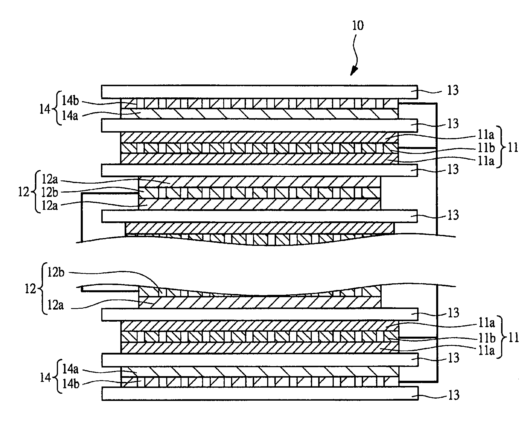
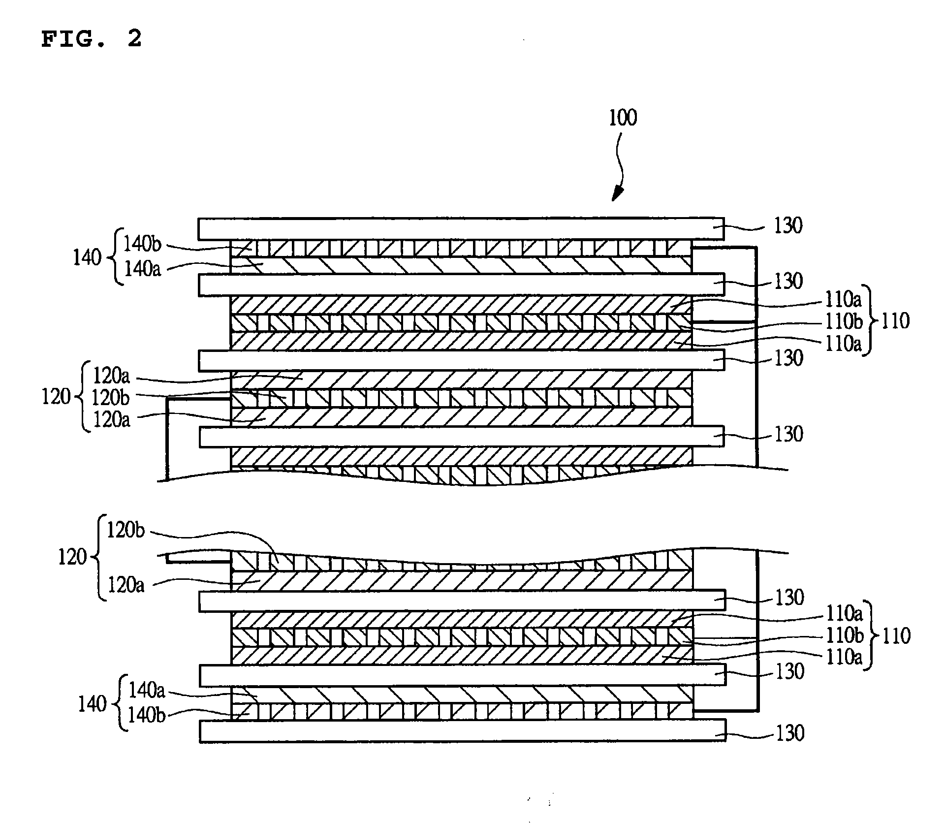
[0030]For example, the lithium ion secondary battery as an electric storage device has a main configuration as shown in FIG. 1. As shown in FIG. 1, the lithium ion secondary battery 10 includes negative electrodes 11 and positive electrodes 12. Each of the negative electrodes 11 and each of the positive electrodes 12 are laminated with a separator 13 interposed therebetween. The negative electrodes 11 are located at the ends of the laminate unit composed of plural negative electrodes 11 and plural positive electrodes 12.

[0031]Lithium electrodes 14, serving as a li...

embodiment 2

[0078]In the embodiment 2, the manner of providing an index according to the measured air permeability will be described. Specifically, the air permeability of an actual electrode varies depending upon the place where the air permeability is measured, to be strict. In other words, there is a variation in the air permeability. Therefore, the manner of knowing the electrode might be different depending upon how to define the measured air permeability as an index.

[0079]As one thing, it is considered that the entire electrode is evaluated at one point on the surface of the mixture layer applied on the current collector. In this case, the result of the measurement at the central point of the electrode surface, where the passing amount of the lithium ions is large, can be utilized. Of course, the air permeability can be measured at the measurement point other than the central point, such as the peripheral of the electrode surface. It is to be noted that the measurement point is preferably...

embodiment 3

[0084]In the embodiment 3, the case in which the air permeability of the electrode is put in a predetermined range beforehand during the manufacture of the electrode will be described.

[0085]The electrode is configured to include a mixture material made of an active material formed on a current collector. The air permeability is expected to be determined according to the combination of the mixture layer and the current collector. For example, it is supposed that the air permeability of the electrode corresponding to the optimum time required for the pre-doping is 50 seconds / 100 mL or more and 2000 seconds / 100 mL. The electrode can be manufactured by combining the mixture layer and the current collector such that the air permeability falls within the above-mentioned range.

[0086]The components such as active materials configuring the mixture material are important configuration components that determine the potential, and the capacity of the electric storage device, for example. Theref...


PUM

PropertyMeasurementUnit
Linear densityaaaaaaaaaa
Fractionaaaaaaaaaa

Abstract

A mixture layer for an electrode is formed on a punched current collector. For example, the mixture layer is made of an active material, conductive assistant, binder, and the like. The mixture layer having the structure described above is formed into a slurry, for example, and applied onto the current collector. The applied mixture layer is dried to fabricate an electrode. The thus formed electrode is used to assemble an electric storage device. Upon the assembly, lithium ions are pre-doped into a negative electrode. The pre-doping time is determined according to air permeability of the electrodes.

Description

CROSS-REFERENCE TO RELATED APPLICATIONS[0001]The disclosure of Japanese Patent Application No. 2008-042367 filed on Feb. 25, 2008 including the specification, drawings, and abstract is incorporated herein by reference in its entirety.BACKGROUND OF THE INVENTION[0002]1. Field of the Invention[0003]The present invention relates to a technology of an electrode, and more particularly, to a technology that is well adaptable to fabricate an electrode having a current collector having holes and a mixture layer, which is made of an active material, formed on the current collector.[0004]2. Description of the Related Arts[0005]In the recent situation where the environmental issue, particularly the vehicle-exhaust gas emission, is widely talked about, efforts are made to develop environment-friendly electric vehicles and the like. In the electric vehicle development, the strong development effort is focused on the electric storage device to be used as a power source. Many types of electric sto...

Claims


Application Information

Patent Timeline
IPC IPC(8): H01M4/40H01G9/042H01M4/02H01G9/00H01G11/22H01G11/42H01G11/50H01G11/70H01M4/13H01M4/139
CPCH01G11/86H01M4/13H01M4/139H01M10/0525Y10T29/49108Y02E60/122Y02E60/13H01G11/26H01M2004/021Y02E60/10H01M10/052
Inventor UTSUNOMIYA, TAKASHINAGAI, MITSURUNAKAZATO, KUNIOANDO, NOBUO
Owner FUJI JUKOGYO KK
Learn More