
Method and apparatus for coherent analog RF photonic transmission

a photonic transmission and analog technology, applied in the field of analog rf photonic communication, can solve the problems of nonlinear response of eam and mzm, difficult to achieve high-speed modulation and low noise with direct modulation of laser diodes, and undesirable harmonic distortion of nonlinear response, etc., and achieve high fidelity

Inactive Publication Date: 2009-08-27
CELIGHT
View PDF58 Cites 89 Cited by
  • Summary
  • Abstract
  • Description
  • Claims
  • Application Information

AI Technical Summary

Benefits of technology

"The present invention is about a high fidelity analog RF photonic system that can transmit and receive RF or microwave signals using a linear RF-to-optical conversion unit and a coherent demodulator. The system includes a transmitter and a receiver with a polarization beam combiner and a polarization rotator to align the polarization states of the light beams. The system can transmit and receive signals in fiber, free space, air, or water. The technical effects of this invention include a true linear modulation and demodulation response without the need for an OpLL or narrow-linewidth lasers, and improved signal quality and stability."

Problems solved by technology

High-speed modulation and low noise is difficult to achieve with direct modulation of laser diodes.
However, the transfer response of EAM and MZM is not truly linear.
The nonlinear response produces undesirable harmonic distortion.
In addition, for analog photonic transmission in optical fiber IM gives rise to signal distortion as a result of fiber nonlinearities.
Such a fast OPLL and narrow-linewidth lasers place limits on the performance and incur high cost of the RF photonic system.
Furthermore, the standard optical mixing technique has a nonlinear sinusoidal response which limits the link performance such as the dynamic range.

Method used


Image

  • Method and apparatus for coherent analog RF photonic transmission
  • Method and apparatus for coherent analog RF photonic transmission
  • Method and apparatus for coherent analog RF photonic transmission

Examples


Embodiment Construction

[0020]The foregoing description of a preferred embodiment of the invention has been presented for purposes of illustration and description. It is not intended to be exhaustive or to limit the invention to the precise form disclosed, and obviously many modifications and variations are possible in the light of the above teaching.

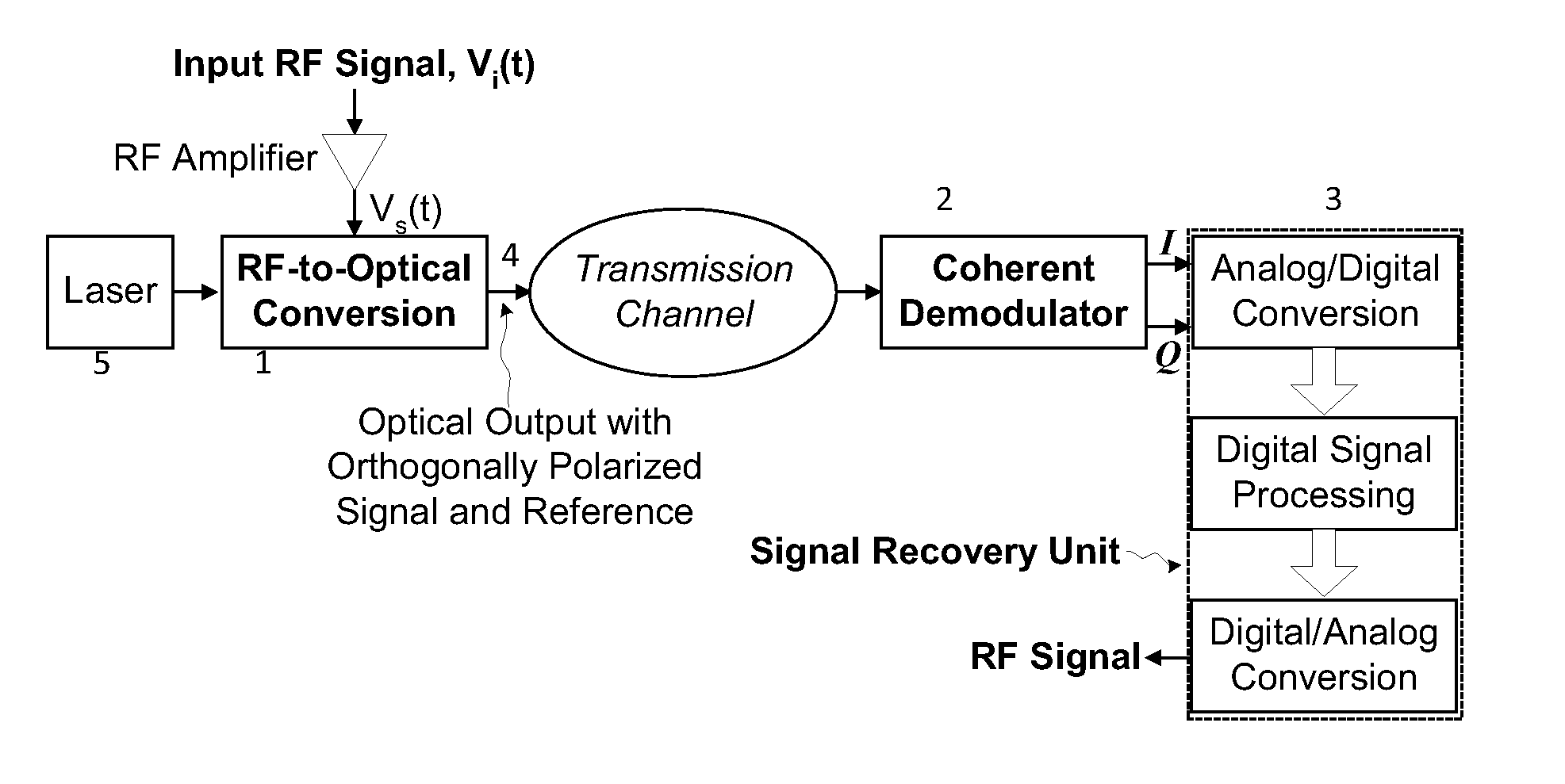
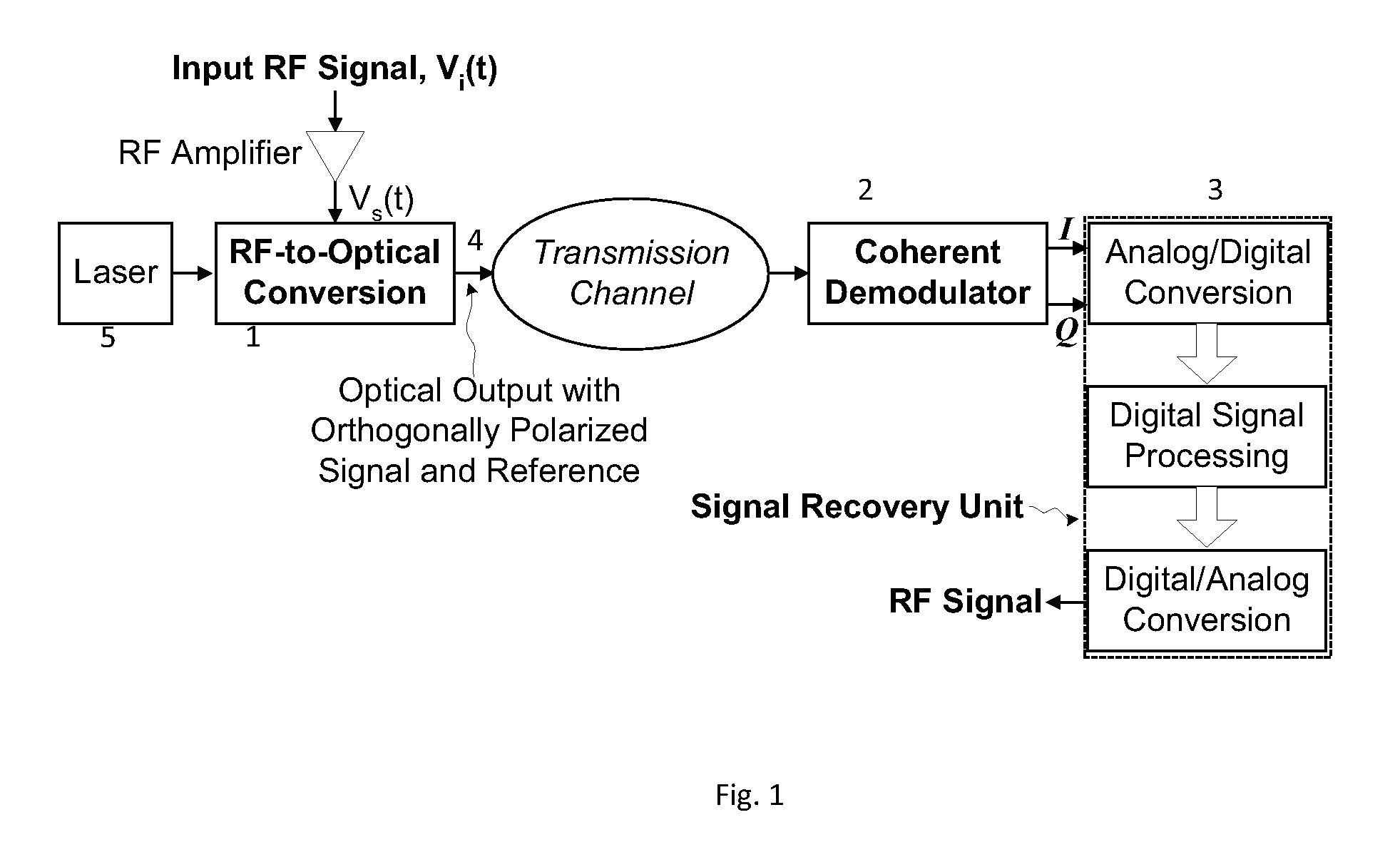
[0021]FIG. 1 shows a schematic block diagram of an analog RF photonic communications system according to an embodiment of the present invention. The optical carrier signal is generally transmitted along a transmission channel to a receiver where it is demodulated to recover the RF data. The transmission channel may include optical fibers, line-of-sight (atmosphere or space) or non-line-of-sight free-space (atmosphere only), and underwater environment.

[0022]Key components of the embodiment are the RF-to-optical conversion unit 1, the coherent demodulator 2, and the signal recovery unit 3 (FIG. 1). Details of these key components are described next.

[0023]The out...


PUM


Abstract

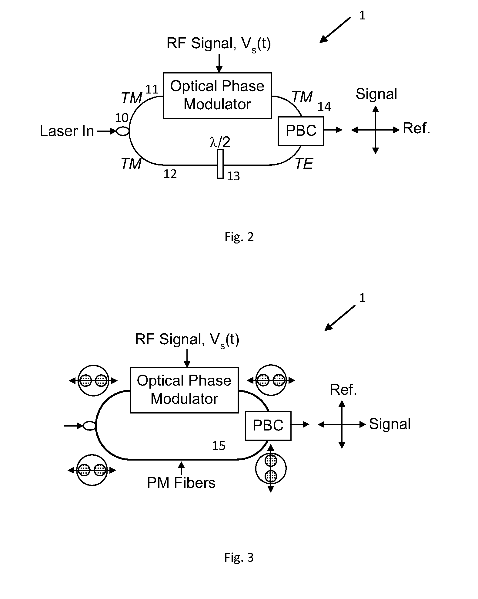
A system for high fidelity analog RF photonic communications is disclosed wherein linear phase modulation and linear coherent demodulation is included. A single optical beam with a phase-modulated signal optical carrier combined with an orthogonally polarized reference unmodulated optical carrier is transmitted simultaneously. At the receiver, the polarization of the reference carrier is transform to match that of the signal followed by coherent detection. An in-phase and quadrature-phase component of the homodyne signal is generated where they are digitized and processed to recover the original RF signal.

Description

FIELD OF INVENTION[0001]This invention relates generally to analog RF photonic communications with linear phase modulation and linear coherent demodulation.BACKGROUND[0002]Analog RF photonics communication requires high linearity to meet the stringent requirements on dynamic range and signal-to-noise ratio for applications such as communications, radar, and electronic warfare. Conventional approach for analog RF photonics employs intensity modulation (IM) to transfer the baseband RF signal onto an optical carrier. This can be achieved via directly modulated semiconductor laser or external modulator such as semiconductor electro-absorption modulator (EAM) or electro-optic lithium niobate Mach-Zehnder modulator (MZM). High-speed modulation and low noise is difficult to achieve with direct modulation of laser diodes. External modulation using an EAM or a quadrature-biased MZM provides high-speed operation without additional optical noise. However, the transfer response of EAM and MZM i...

Claims


Application Information

Patent Timeline
Patent Type & Authority Applications(United States)
IPC IPC(8): H04B10/04
CPCH04B10/61
Inventor CHO, PAK SHINGACHIAM, YAAKOV
Owner CELIGHT
Learn More