
Hygiene-maintaining device of an underpressure-activated valve for a drinking receptacle

a technology of underpressure activation valve and hygiene-maintaining device, which is applied in the direction of drinking receptacles, manufacturing tools, transportation and packaging, etc., can solve the problems of bacteria mixing, bacterial growth in liquid residues, and potential bad odour

Inactive Publication Date: 2009-08-27
SMARTSEAL AS
View PDF5 Cites 18 Cited by
  • Summary
  • Abstract
  • Description
  • Claims
  • Application Information

AI Technical Summary

Benefits of technology

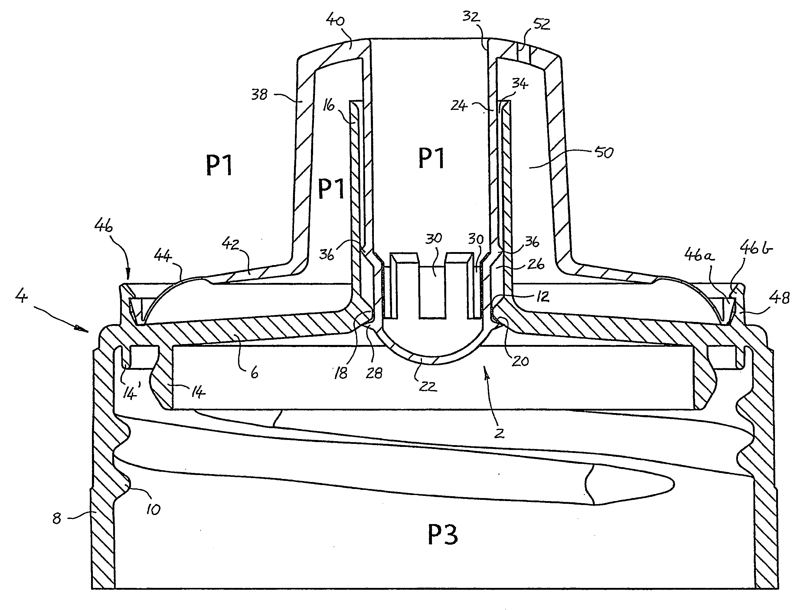
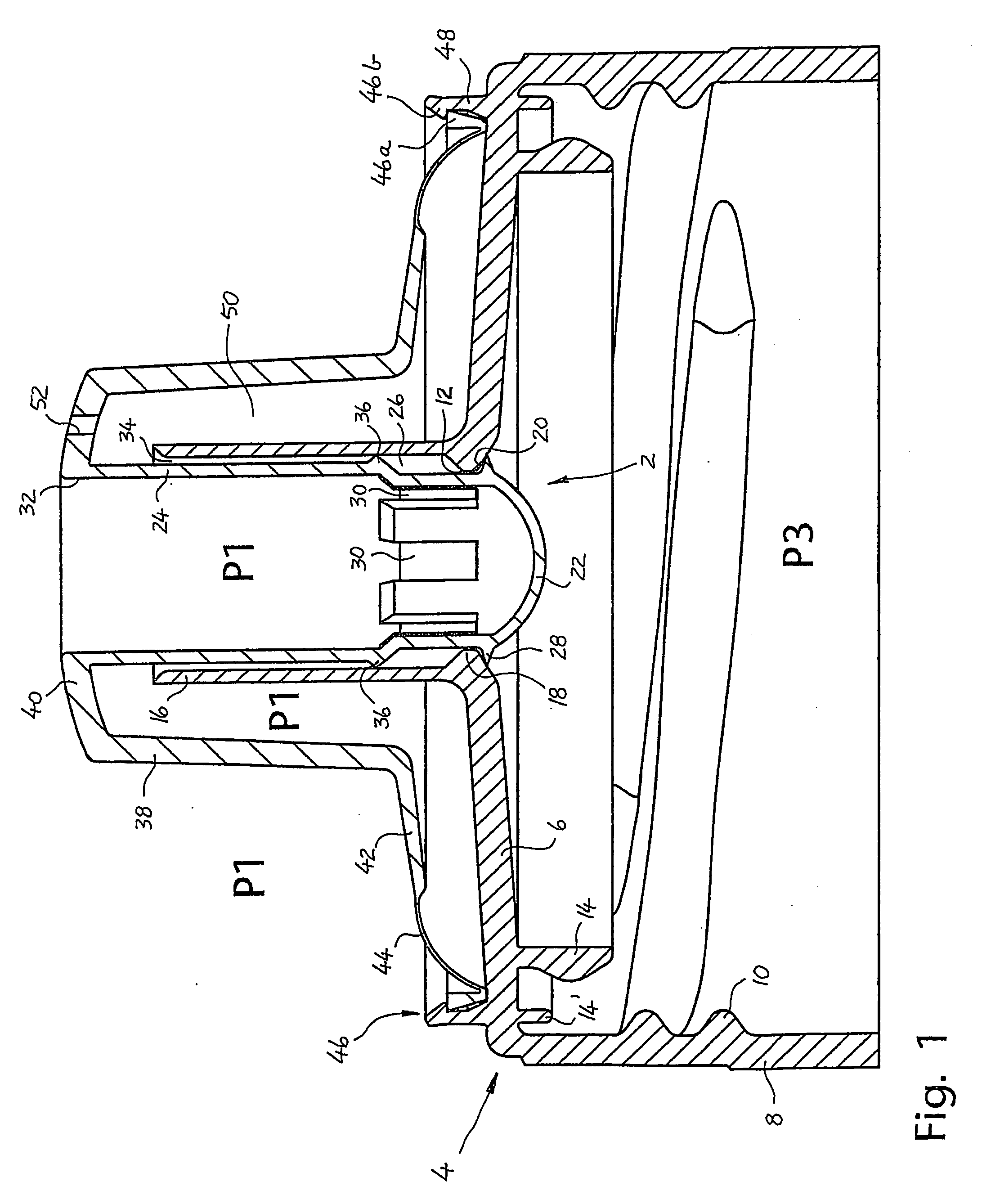
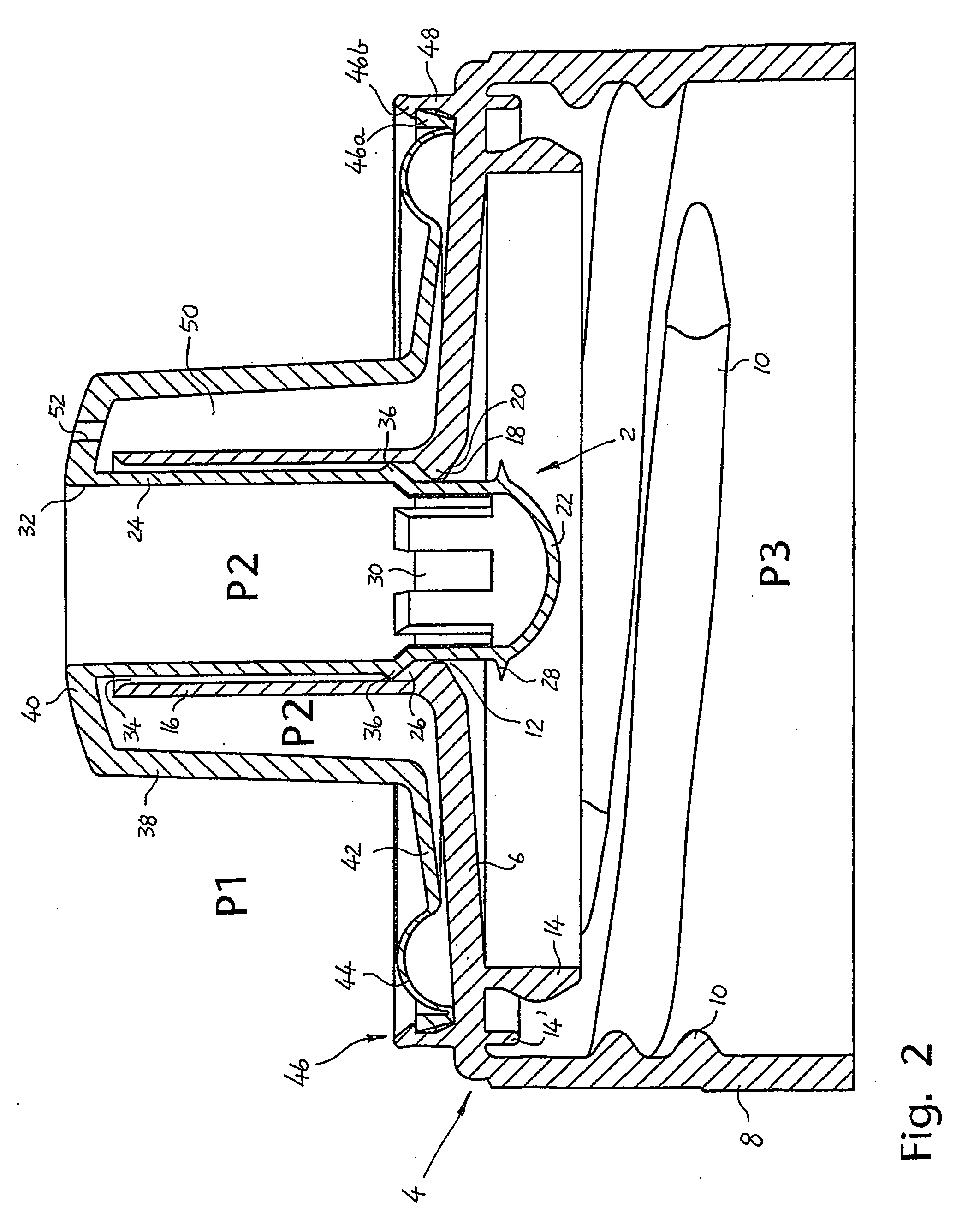
[0020]Even though the suction chamber and the liquid's outlet path are physically separated in order to fully or partially prevent liquid residues from entering into the suction chamber, said at least one activation opening and a downstream portion, preferably a downstream drinking opening, of the liquid outlet path may be arranged in proximity of each other. In some embodiments, the activation opening may also include a portion of the liquid outlet path. Preferably, the drinking opening is provided within a drinking spout of a cap for the drinking receptacle. Such a relative placement of the activation opening(s) and said liquid outlet portion renders possible to establish a valve-activating underpressure P2 in the suction chamber, simultaneously allowing liquid to flow past the suction chamber and out of the liquid outlet portion.
[0022]An activation opening may also be provided with an airflow control device for controlling the course of venting in and out of the activation opening. The airflow control device may be arranged so as to promote airflow in one direction and restrain airflow in the opposite direction. For example, the device may be arranged in a manner allowing air that is sucked out of the suction chamber to underpressure-activate the operating member, to flow substantially easier and at a higher rate than that of a subsequent and oppositely directed airflow flowing into the suction chamber in order to balance the pressure therein. The flow control device may be used to provide rapid flow and short response time when discharging air from the suction chamber, but slow air influx into the suction chamber on the other hand accompanied with a delayed closing of the valve in order to balance the pressure in said drinking receptacle.
[0023]The flow control device may comprise two or more flexible flaps that are attached around the activation opening, preferably within and around the wall thereof, and which project obliquely out from the suction chamber. Whilst in position of rest, the flaps, and particularly the free ends thereof, are placed in proximity of each other, possibly fully or partially in contact with each other. Assembled in this manner, the flaps define a conical shape or other tapered shape, in which the cone tip or taper tip faces outwards from the suction chamber. When admitting air into the suction chamber, the airflow will force the flaps against each other and thus constrict the flow section of the activation opening, which has a flow-restraining effect on the airflow. When discharging air from the suction chamber, the airflow will force the flaps away from each other and thus increase said flow section, which has a flow-promoting effect on the airflow and facilitates the course of discharge. Such a flow control device may also contribute to prevent any liquid residues from entering into the suction chamber. Moreover, one or more activation openings each may be connected to or provided with a unidirectional valve (check valve) allowing air discharge from the suction chamber only. Preferably, such unidirectional valves should be placed closest to said downstream liquid outlet portion in order to minimize the risk of influx of liquid residues into the suction chamber.

Problems solved by technology

Depending on the type of liquid contained in the drinking receptacle, this may result in bacterial growth in the liquid residues and potential bad odour emanating therefrom.
As such, there is a risk of bacteria being mixed into subsequent liquid outflows so as to create unhygienic conditions therein, which is undesirable.

Method used


Image

  • Hygiene-maintaining device of an underpressure-activated valve for a drinking receptacle
  • Hygiene-maintaining device of an underpressure-activated valve for a drinking receptacle
  • Hygiene-maintaining device of an underpressure-activated valve for a drinking receptacle

Examples


Embodiment Construction

OF EMBODIMENTS OF THE INVENTION

[0038]The valve embodiments according to FIGS. 1-3 have many similarities to some examples of embodiments in said patent NO 316506 (Naesje), and which concerns a device for underpressure-activation of a valve for a drinking receptacle. The present valve embodiments employ the same principle of operation as the valves according to NO 316506.

[0039]FIGS. 1 and 2 show an underpressure-activated valve 2 provided on the outside of a cap 4 consisting of an end wall 6 and a circular mantel 8. The mantel 8 is provided with internal threads 10 for connection to a bottle (not shown). Whilst in position of use, the cap 4 and the bottle have an internal pressure P3 that may be larger than the ambient pressure P1 of the bottle, for example when the bottle contains a carbonated liquid. In this connection, the end wall 6 constitutes the above-mentioned partition between the inner space of the bottle and the outer surroundings thereof. The partition 6 is provided with ...


PUM

PropertyMeasurementUnit
pressureaaaaaaaaaa
perimeteraaaaaaaaaa
flexibleaaaaaaaaaa

Abstract

A hygiene-maintaining device of an underpressure-activated valve (2) for a drinking receptacle. Whilst in position of use, the valve (2) encloses a downstream side of an outlet opening (12) in a partition (6) associated with the drinking receptacle. The partition (6) may be a wall portion of the drinking receptacle, or a wall portion of a cap (4) for the receptacle. The valve (2) comprises a movable operating member, a bracing element (24, 70) and a seal member (22) that, whilst in position of rest, seals off said partition opening (12). The operating member is connected to a suction chamber (50) within which an underpressure (P2) may be established in order to activate and move the operating member into a valve-opening position. Thereby, liquid may flow out via the partition opening (12) and further onwards through a liquid outlet path in the valve (2), the operating member being pressure-balanced against the ambient pressure (P1) of the drinking receptacle. The suction chamber (50) is connected to at least one activation opening (52) through which the underpressure (P2) in the chamber (50) may be established. The distinctive characteristic of the invention is that the suction chamber (50) is separated from said liquid outlet path through the valve (2), which fully or partially prevents liquid residues from entering into the suction chamber (50) so as to create subsequent unhygienic conditions therein.

Description

AREA OF THE INVENTION[0001]The present invention concerns a hygiene-maintaining device of an underpressure-activated valve for a drinking receptacle. The valve is used to control a pressurized or non-pressurized liquid outflow from the receptacle. The liquid may be a liquid nutrient, for example a refreshing drink or a milk-containing product, and the liquid may be pressurized from carbon dioxide or some other suitable gas. Preferably, the present hygiene-maintaining device is intended for use in connection with a drinking spout or similar drinking device for the drinking receptacle, or in connection with a cap for the drinking receptacle. For example, the drinking receptacle may be a bottle, soft drink bottle, feeding bottle, carton, pouch, can, tube, paper drinking cup or a plastic cup.BACKGROUND OF THE INVENTION[0002]The invention is based on the use of an underpressure-activated valve of a type that includes a suction chamber for opening the valve to liquid outflow from the drin...

Claims


Application Information

Patent Timeline
Patent Type & Authority Applications(United States)
IPC IPC(8): B65D47/04B29C39/36B29C33/44B29C45/44B65D47/20B67B
CPCB29C33/442A47G19/2272B65D47/2081B29C45/4407
Inventor NAESJE, KJETIL
Owner SMARTSEAL AS
Learn More