
Oil and gas well completion system and method of installation

Active Publication Date: 2009-08-27
DRIL QUIP
View PDF99 Cites 43 Cited by
  • Summary
  • Abstract
  • Description
  • Claims
  • Application Information

AI Technical Summary

Benefits of technology

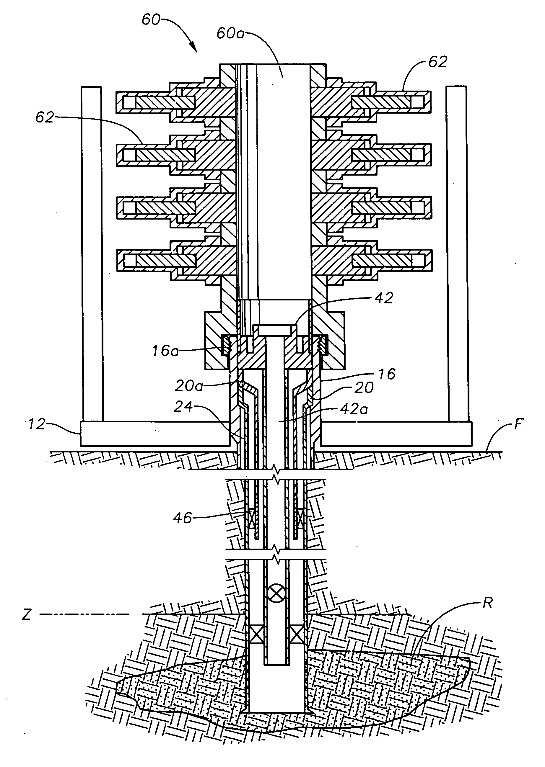
[0020]A completion system, and a corresponding method, for completing a subsea well, where the well includes a wellhead and a tubing hanger disposed in the wellhead and supports a string of production tubing, allows for angular alignment-free assembly of the subsea well. The completion system includes a series of circumferential channels formed in a well completion device at a boundary between the tubing hanger and the well completion device. The circumferential channels provide complete circular fluid paths with respect to the tubing hanger and the well completion device. At least one supply bore is in communication with each circumferential channel and is and oriented to supply a fluid to the circumferential channel, and at least one drain bore in communication with each circumferential channel and is oriented to remove fluid from the circumferential channel. Finally a circumferential electrical connector couples the tubing hanger and the completion device. The circumferential channels and bores provide fluid services between the completion device and the tubing hanger and the electrical connector provides electrical services to the tubing hanger. The completion system allows the fluid and electrical services to be provided without requiring any angular alignment between the tubing hanger and the completion device.

Problems solved by technology

The costs associated with such completion systems which require angular orientation are high.
The cost to modify a BOP stack for orientation during the drilling process requires temporary abandonment of the well.
This procedure also requires temporary abandonment of the well, because the procedure can not be employed during the drilling of the well, and because the casing hangers require a full bore to the wellhead housing.
As described above, temporary abandonment of a well costs about $600,000 per / day.

Method used


Image

  • Oil and gas well completion system and method of installation
  • Oil and gas well completion system and method of installation
  • Oil and gas well completion system and method of installation

Examples


Embodiment Construction

will refer to the following drawings, in which like numerals indicate like items, and in which:

[0022]FIG. 1 illustrates a wellhead, with a casing string landed therein, of a subsea oil or gas well in a schematic, partial sectional elevation view;

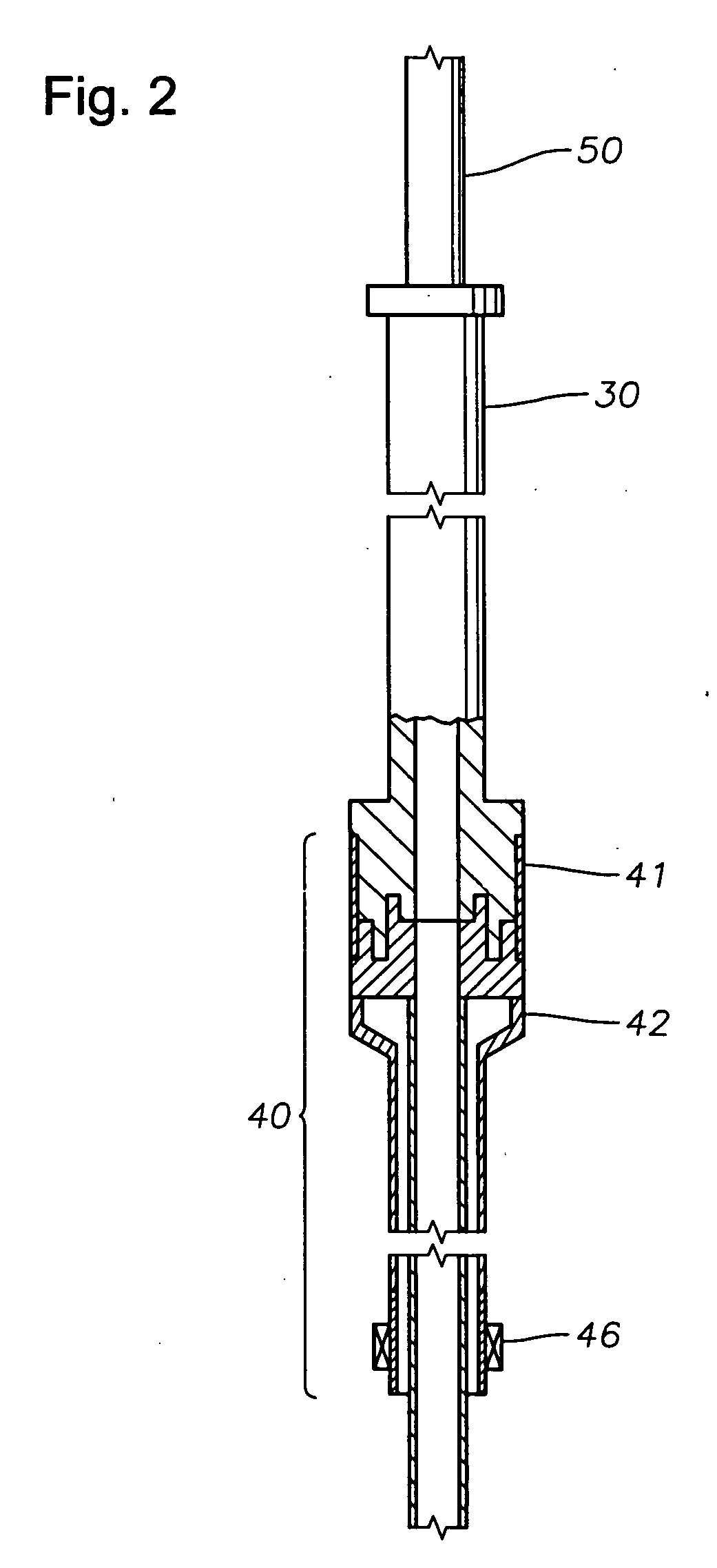
[0023]FIG. 2 illustrates an exemplary tubing hanger running tool attached to a tubing hanger and production tubing, in partial sectional view, for installation in the subsea well of FIG. 1;

[0024]FIG. 3 illustrates the subsea oil and gas well of FIG. 1 with a blowout preventer (BOP) latched to a wellhead, with the tubing hanger and production tubing installed therein;

[0025]FIGS. 4A-4C illustrate the subsea well of FIG. 1 with the BOP removed and a tubing hanger installed;

[0026]FIG. 5 illustrates the subsea well of FIG. 1 with a Christmas tree installed;

[0027]FIGS. 6A-8C are simplified schematic views of embodiments of angular alignment-free connection configurations for a subsea oil or gas well; and

[0028]FIGS. 9-14 are cutaway sectional views...


PUM


Abstract

A completion system, and a corresponding method, for completing a subsea well, where the well includes a wellhead and a tubing hanger disposed in the wellhead and supports a string of production tubing, allows for angular alignment-free assembly of the subsea well. The completion system includes a series of circumferential channels formed in a well completion device at a boundary between the tubing hanger and the well completion device. The circumferential channels provide complete circular fluid paths with respect to the tubing hanger and the well completion device. At least one supply bore is in communication with each circumferential channel and is and oriented to supply a fluid to the circumferential channel, and at least one drain bore in communication with each circumferential channel and is oriented to remove fluid from the circumferential channel. Finally a circumferential electrical connector couples the tubing hanger and the completion device. The circumferential channels and bores provide fluid services between the completion device and the tubing hanger and the electrical connector provides electrical services to the tubing hanger. The completion system allows the fluid and electrical services to be provided without requiring any angular alignment between the tubing hanger and the completion device.

Description

CROSS-REFERENCE TO RELATED APPLICATIONS[0001]This application is a continuation-in-part of pending U.S. patent application Ser. No. 12 / 049,093, filed Mar. 14, 2008, entitled “Universal Tubing Hanger Suspension Assembly and Well Completion System and Method of Using Same,” which is a continuation of U.S. patent application Ser. No. 11 / 216,277, filed Aug. 31, 2005, entitled “Universal Tubing Hanger Suspension Assembly and Well Completion System and Method of Using Same,” now U.S. Pat. No. 7,419,001, which claims priority to U.S. Provisional Application Ser. No. 60 / 682,250 filed May 18, 2005, all of which applications are hereby incorporated by reference in their entirety. This application also claims the benefit of U.S. Provisional Application Ser. No. 61 / 126,302 entitled “Oil and Gas Well Completion System and Method for Installation,” filed on May 2, 2008, and which is incorporated by reference in its entirety.BACKGROUND[0002]1. Field of the Invention[0003]The field of the invention...

Claims


Application Information

Patent Timeline
IPC IPC(8): E21B33/035E21B23/00E21B33/043E21B33/064E21B43/01E21B41/00E21B34/04
CPCE21B23/01E21B33/043E21B33/0422
Inventor BROUSSARD, EARL
Owner DRIL QUIP
Learn More