
Etching endpoint determination method

a technology of endpoint determination and etching, which is applied in the direction of fluid pressure measurement, semiconductor/solid-state device testing/measurement, instruments, etc., can solve the problems of excessive etching of the film underlying the film that should be etched, deterioration of workpiece shape, and detection is susceptible to noise components contained in signals

Inactive Publication Date: 2009-08-27
HITACHI HIGH-TECH CORP
View PDF2 Cites 14 Cited by
  • Summary
  • Abstract
  • Description
  • Claims
  • Application Information

AI Technical Summary

Benefits of technology

The present invention provides an etching endpoint determination technology that can accurately detect the endpoint of etching processing in an early manner. This is achieved by sampling light emitted by the plasma produced in the vacuum processing chamber and computing a regression line and distances in a time-base direction between the regression line and the time-sequential data. This technology can improve the accuracy and efficiency of etching processing.

Problems solved by technology

For example, in determination of an endpoint of etching, in case an endpoint determination time lags only several seconds, a film underlying a film that should be etched is excessively etched.
Consequently, a workpiece shape deteriorates.
Therefore, when the aperture ratio is low, the detection is susceptible to a noise component contained in a signal.
It is hard to detect an etching endpoint accurately in an early stage.

Method used


Image

  • Etching endpoint determination method
  • Etching endpoint determination method
  • Etching endpoint determination method

Examples


Embodiment Construction

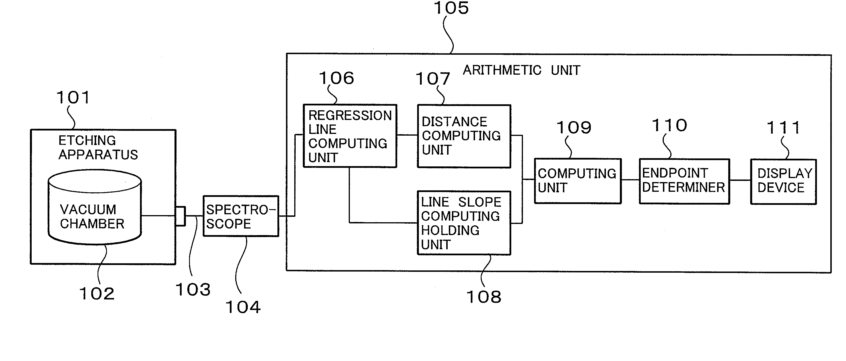
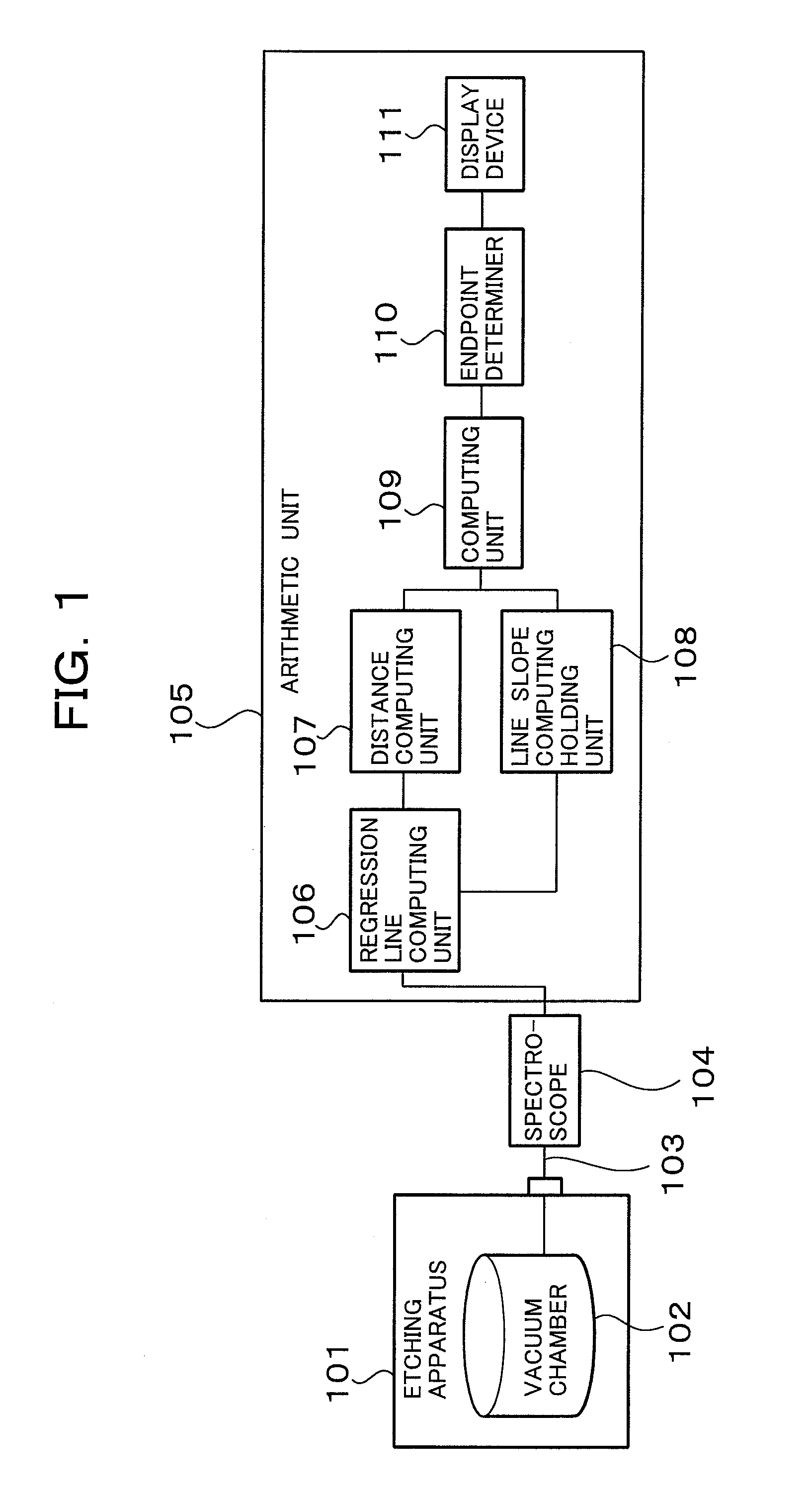
[0026]Referring to the appended drawings, the best embodiment will be described below. FIG. 1 is an explanatory diagram showing an etching endpoint determination system in accordance with the present embodiment. An etching apparatus 101 includes a vacuum chamber 102. An etching gas is introduced into the vacuum chamber 102 via a gas introduction means that is not shown. Microwave power or the like is fed to the introduced etching gas in order to decompose the etching gas so as to produce plasma. The plasma is used to perform etching processing on a sample such as a wafer stored in the vacuum chamber.

[0027]A spectroscope is used to measure the spectrum of light of a specific wavelength emitted by plasma generated in the vacuum chamber during etching processing, and the signal component of the specific wavelength acquired through the spectral measurement is fetched into an arithmetic unit 105. The arithmetic unit 105 is formed with, for example, a personal computer (PC).

[0028]The fetc...


PUM

PropertyMeasurementUnit
timeaaaaaaaaaa
frequencyaaaaaaaaaa
luminous intensityaaaaaaaaaa

Abstract

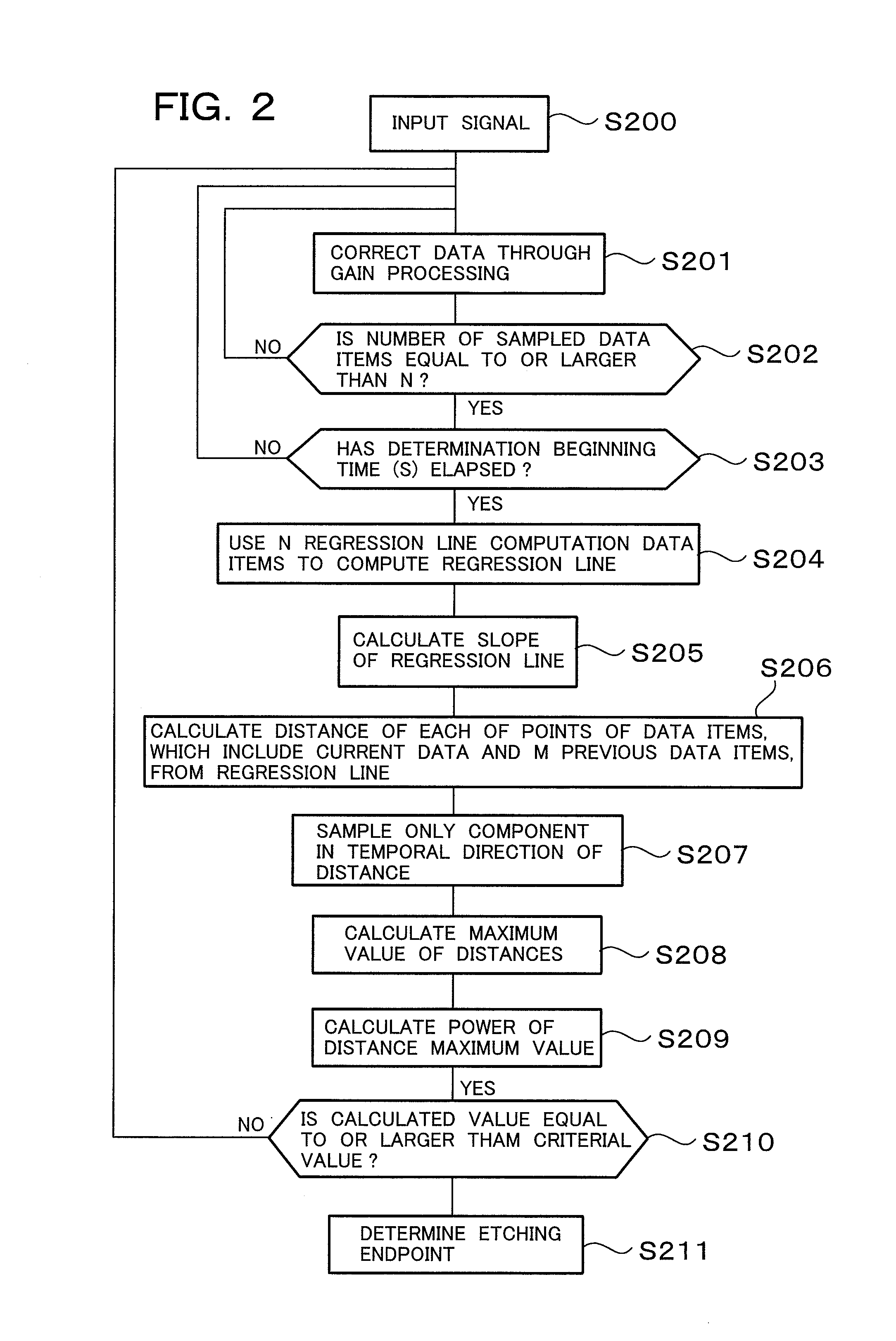
A microscopic change in a luminous intensity occurring near an etching endpoint is accurately detected, whereby the endpoint of etching is quickly determined. An etching endpoint determination method for determining an endpoint of etching processing in a plasma etching apparatus that introduces a processing gas into a vacuum chamber, produces plasma by feeding high-frequency energy to a introduced processing gas, and uses the produced plasma to perform plasma processing on a workpiece stored in the chamber includes: a step of sampling light of a pre-set wavelength from light emitted by the plasma produced in the vacuum chamber, acquiring as time-sequential data the luminous intensity of the sampled light of the specific wavelength, and computing a regression line on the basis of the acquired time-sequential data; and a step of computing distances in a time-base direction between the regression line and the time-sequential data which are obtained at the first step. An endpoint of etching processing is determined based in the distances in the time-base direction obtained at the second step.

Description

BACKGROUND OF THE INVENTION[0001]1. Field of the Invention[0002]The present invention relates to an etching endpoint determination method, or more particularly, to an etching endpoint determination method making it possible to highly precisely determine an endpoint of etching processing to be performed by utilizing plasma discharge.[0003]2. Description of the Related Art[0004]In dry etching processing of a semiconductor wafer, the luminous intensity of light of a specific wavelength under plasma light emission changes along with the progress of etching of a specific film. The change in the luminous intensity of the light of the specific wavelength under plasma light emission is detected during the etching processing of the semiconductor wafer. Based on the result of the detection, an etching endpoint for the specific film can be detected.[0005]For example, Japanese Patent Application Laid-Open Publication No. 2004-79727 reads that: a plasma-emitted light signal to be generated in an...

Claims


Application Information

Patent Timeline
Patent Type & Authority Applications(United States)
IPC IPC(8): C23F1/00
CPCH01J37/32963H01J37/32935H01L22/00H01L21/00
Inventor UCHIDA, HIROSHIGESHIRAISHI, DAISUKEIKUHARA, SHOJIKAGOSHIMA, AKIRA
Owner HITACHI HIGH-TECH CORP
Learn More