
Method for Functionally Testing an Ultrasonic Sensor

a technology of ultrasonic sensors and functional testing, applied in the direction of transmission monitoring, instruments, and reradiation, can solve problems such as sudden failures or shocks that occur unexpectedly

Inactive Publication Date: 2009-08-20
ROBERT BOSCH GMBH
View PDF6 Cites 30 Cited by
  • Summary
  • Abstract
  • Description
  • Claims
  • Application Information

AI Technical Summary

Benefits of technology

[0003]Against this background, the method according to the present invention for functionally testing an ultrasonic sensor has the advantage that a signal emitted by another sensor for functional testing purposes, is compared to a variable limit value for the amplitude signal. This makes it possible, in particular, to detect a gradual fading of the sensor, caused, for example, by icing, dirt accumulation, aging or other interference effects. Moreover, for a more effective functional testing, it is possible to adapt the sensor as precisely as possible to its installation position, to obtain reliable information about the sensor functioning. As a result, more reliable information is obtained as to whether the sensor is functioning perfectly.
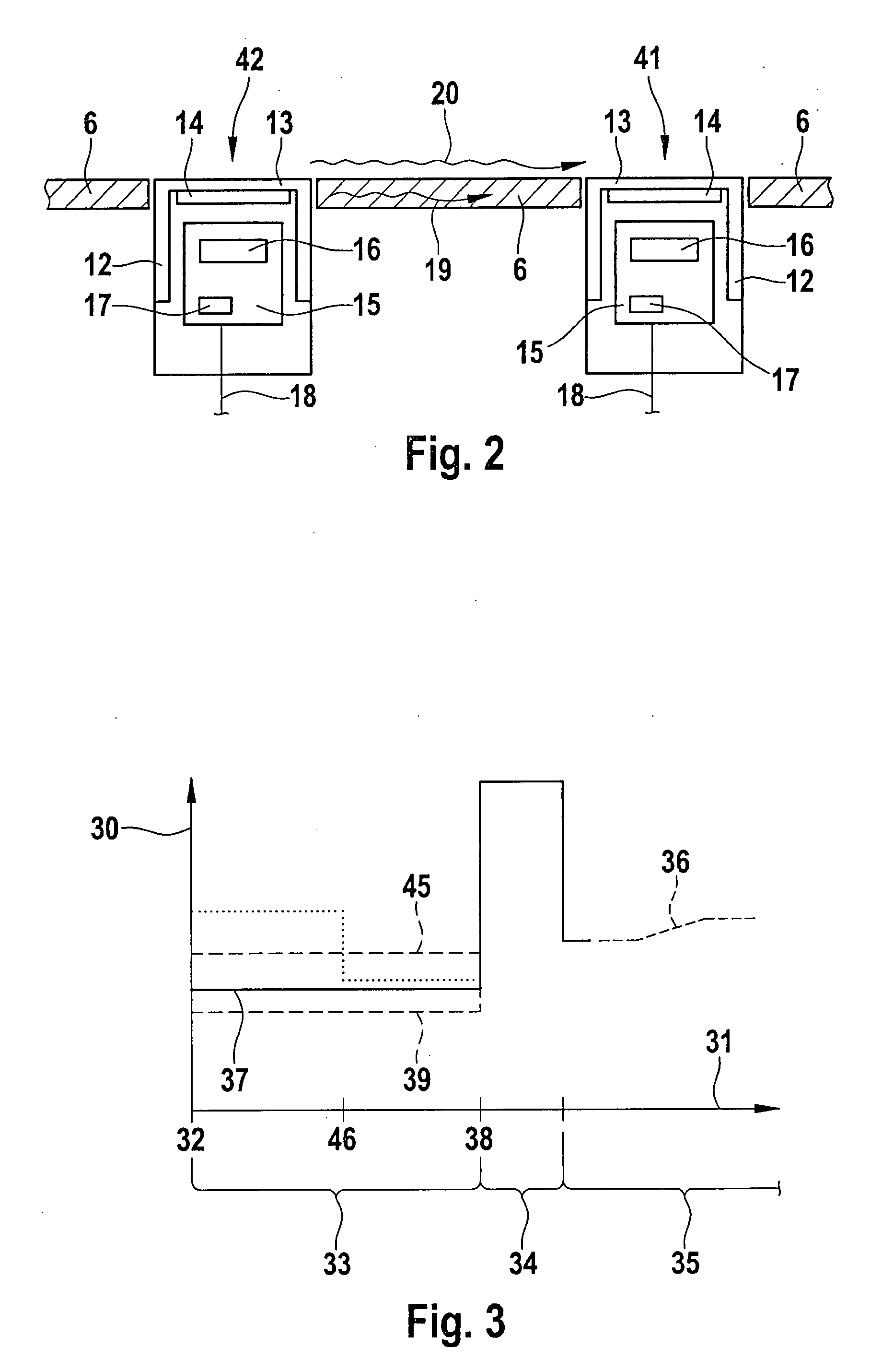
[0005]In addition, it is beneficial to vary the limit value over the duration of the time evaluation window. In particular, by varying the limit value during the evaluation window, it is possible to provide different limit values for signals that are emitted by various other ultrasonic sensors. It is then expected that a signal which is transmitted by a more distant sensor and which has a longer propagation time than a signal transmitted by a more proximate sensor, will also have a lower amplitude. By varying the limit value during the evaluation window, a signal reception may be detected by both sensors, thereby enhancing the reliability of the functional test. In some instances, this also makes it possible to infer a functioning of other ultrasonic sensors as transmitters.

Problems solved by technology

In particular, only stochastically occurring errors or sudden failures during the measurement operation may be detected in this manner.

Method used


Image

  • Method for Functionally Testing an Ultrasonic Sensor
  • Method for Functionally Testing an Ultrasonic Sensor
  • Method for Functionally Testing an Ultrasonic Sensor

Examples


Embodiment Construction

[0013]The present invention may be employed for any distance measuring devices having ultrasonic sensors. Its use is particularly advantageous for a distance measuring device in a motor vehicle, since a driver relies upon the warnings of a distance measuring device, warning him prior to a collision with obstacles in the vehicle's surrounding field. The certain detection of a loss or a limitation of the detection capability ensures that, in the event of a declining sensor performance, a driver receives feedback to this effect, allowing him to either restore the functional performance of the distance measuring device or to no longer rely on a warning indication therefrom, at least for the duration of the disturbance.

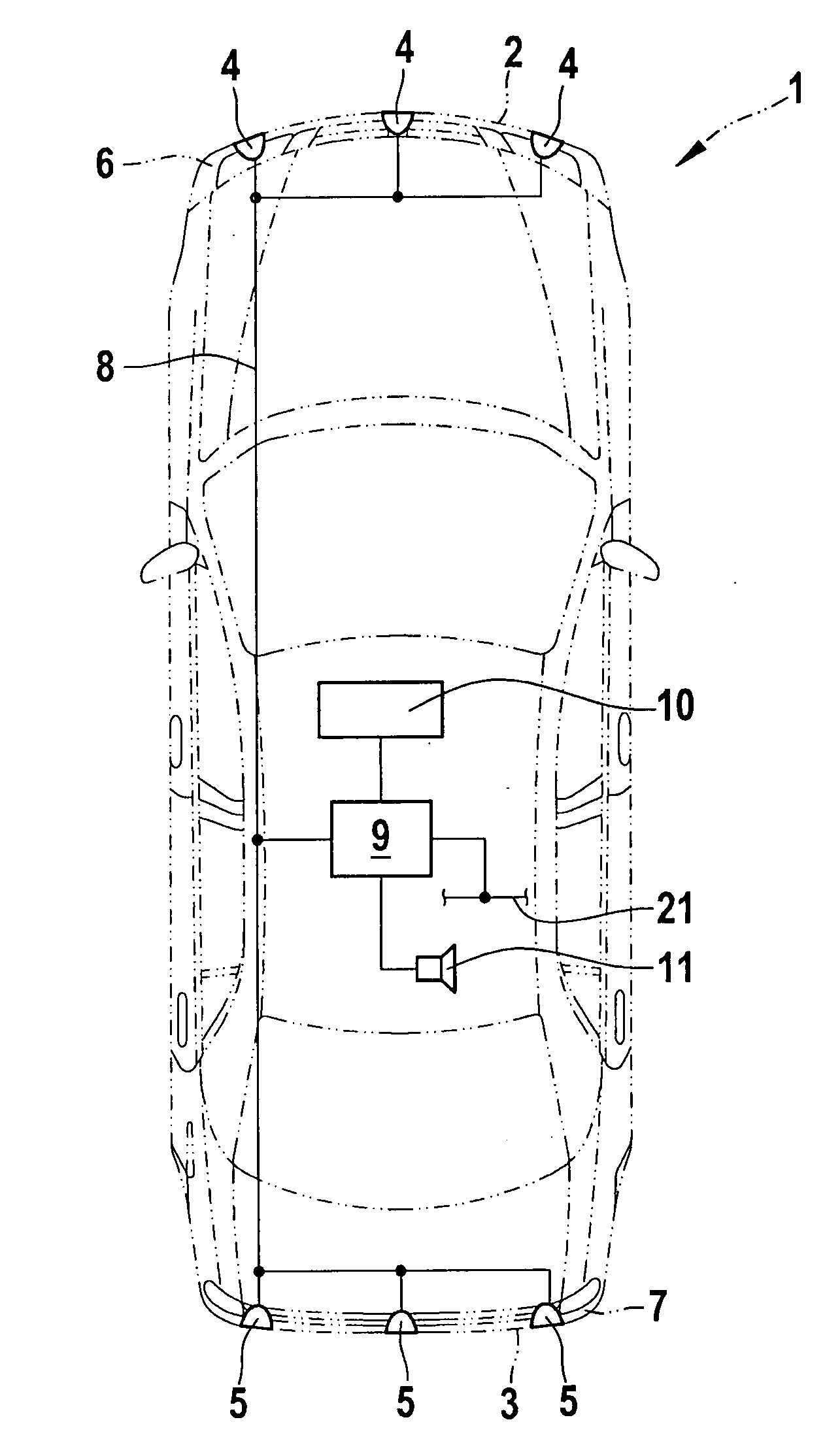
[0014]A motor vehicle 1 is schematically shown in FIG. 1. Ultrasonic sensors 4, 5 are mounted at a front end 2 and a rear end 3, respectively, of motor vehicle 1. In this case, ultrasonic sensors 4, 5 are preferably installed in a front bumper 6, respectively in a rear bum...


PUM


Abstract

A method for functionally testing an ultrasonic sensor in which at least one additional ultrasonic sensor transmits an ultrasound signal, and a functioning of the first sensor is ascertained when the amplitude of the signal transmitted by the first sensor without being reflected off of an external obstacle exceeds a predefined, variable limit value.

Description

BACKGROUND INFORMATION[0001]A device for monitoring vehicle back-up safety systems is described in European Patent Application No. EP 312 845. At least two transmitter / receiver pairs, which each have an assigned electroacoustic transducer and are operated using the sound reflection method, are mounted at the rear end of the vehicle. An acoustic shunt is provided between two adjacent transducers, so that the signal received at any one time from an adjacent transmitter is evaluated as a function monitoring signal.[0002]From German Patent Application No. DE 199 24 755, a distance-sensing device is known, which is used to analyze crosstalk signals between two sensors in order to monitor functioning. In this connection, a received signal is compared to a fixed, predefined threshold.SUMMARY OF THE INVENTION[0003]Against this background, the method according to the present invention for functionally testing an ultrasonic sensor has the advantage that a signal emitted by another sensor for ...

Claims


Application Information

Patent Timeline
Patent Type & Authority Applications(United States)
IPC IPC(8): G01S15/93G01S7/52G01S15/931
CPCG01S7/52004G01S2015/938G01S15/931
Inventor RICHTER, KARL-HEINZPREISSLER, PETER
Owner ROBERT BOSCH GMBH
Learn More