
Brake fluid pressure control device for bar handle vehicle

a technology of brake fluid pressure control and bar handle, which is applied in the direction of brake actuation mechanism, vehicle components, brake systems, etc., can solve the problems of large reaction force in the operation of the brake operation element, unfavorable imparting a rigid feeling to the driver, and designed to improve the operational feeling. , to achieve the effect of improving the operational feeling

Active Publication Date: 2009-08-20
HITACHI ASTEMO LTD
View PDF8 Cites 5 Cited by
  • Summary
  • Abstract
  • Description
  • Claims
  • Application Information

AI Technical Summary

Benefits of technology

[0008]Accordingly, an object of the invention is to provide a brake fluid pressure control device for a bar handle vehicle which is capable of improving the operational feeling when a brake operation element is additionally operated during the interlocked brake control.
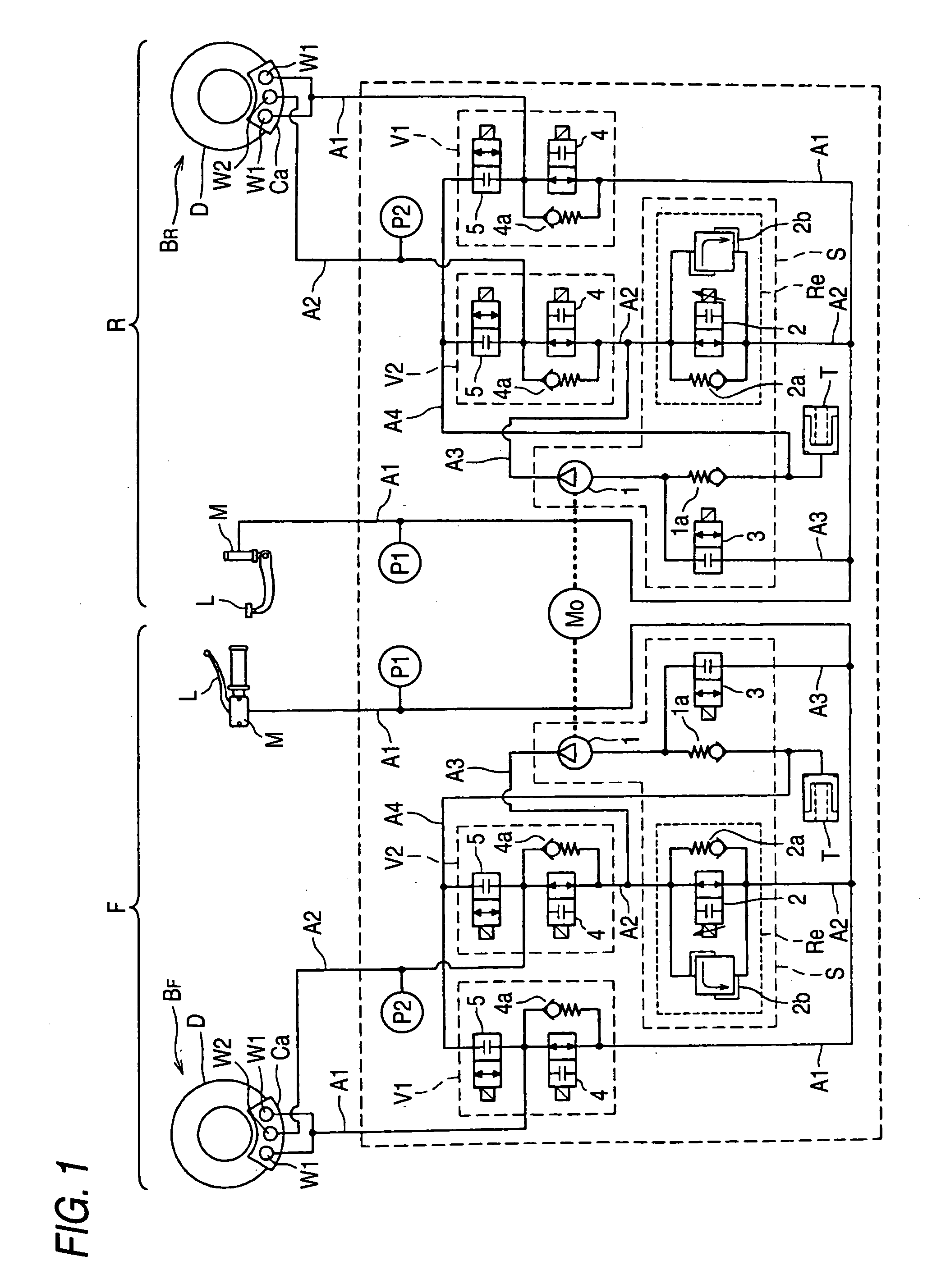
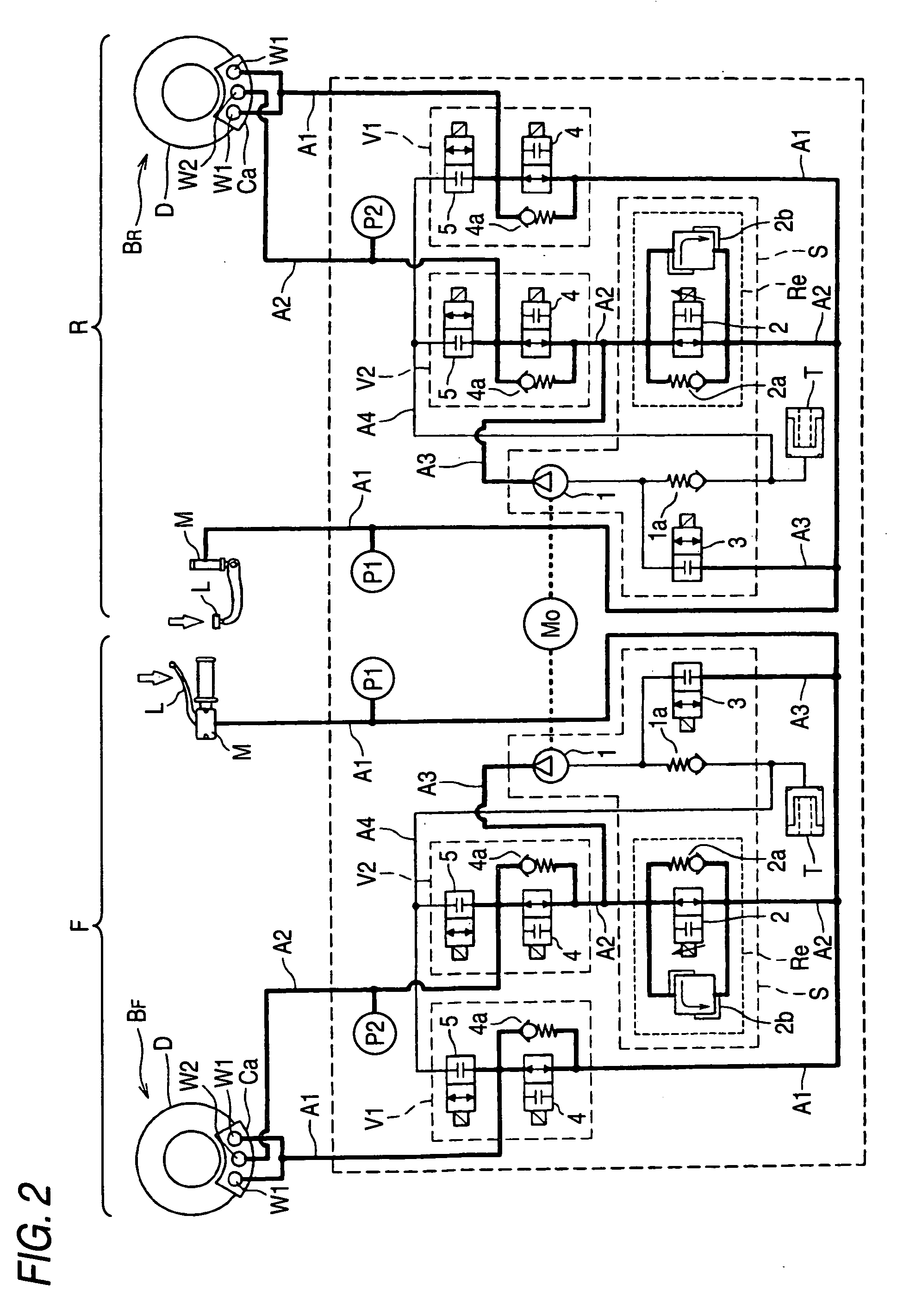
[0018]According to the brake fluid pressure control device for the bar handle vehicle, since the pressure of the second wheel cylinder of one brake system can be boosted by the boosting unit, it is possible to execute the interlocked brake control for allowing the braking force to be generated in the brake of the one brake system in interlocking relation to the operation of the brake operation element corresponding to the other brake system. Moreover, according to the invention, since it is unnecessary to boost the brake fluid pressure in the first wheel cylinder during the interlocked brake control, it becomes possible to alleviate the “rigid feeling” when the brake operation element is operated during the interlocked brake control. Namely, according to the invention, the operational feeling of the brake operation element during the interlocked brake control can be made similar to the operational feeling persisting at the time of normal braking in which the interlocked brake control is not executed.
[0025]To boost the brake fluid pressure in the second wheel cylinder without boosting the brake fluid pressure in the first wheel cylinder, it suffices if the pump is operated with the cut valve closed to supply the brake fluid to the second hydraulic path on a second wheel cylinder side of the cut valve via the suction channel. If the pump is operated with the cut valve closed, the pulsation of the pump is made difficult to be transmitted to the brake operation element, so that it becomes possible to improve the operational feeling when the brake operation element is additionally operated during the interlocked brake control.
[0032]According to this configuration, it becomes possible to execute the antilock brake control in the brake system executing the interlocked brake control.
[0033]Furthermore, the first wheel cylinder and the second wheel cylinder may be formed in one caliper. If such an arrangement is adopted, as compared with a case where the both wheel cylinders are dispersed in different calipers, it becomes possible to reduce the number of component parts, and hence it becomes possible to lightweight the bar handle vehicle.
[0034]According to the invention, it becomes possible to improve the operational feeling when the brake operation element is additionally operated during the interlocked brake control.

Problems solved by technology

However, when the brake operation element of the front wheel is additionally operated in such a state, since the pressure in the hydraulic path has been already boosted, the reaction force in the operation of the brake operation element is large, thereby unfavorably imparting a “rigid feeling” to the driver.
However, its resolving means is to ensure not to perform the interlocked brake control to the front wheel brake, and is not designed to improve the operational feeling at the time of an additional operation while performing the interlocked brake control.

Method used


Image

  • Brake fluid pressure control device for bar handle vehicle
  • Brake fluid pressure control device for bar handle vehicle
  • Brake fluid pressure control device for bar handle vehicle

Examples


Embodiment Construction

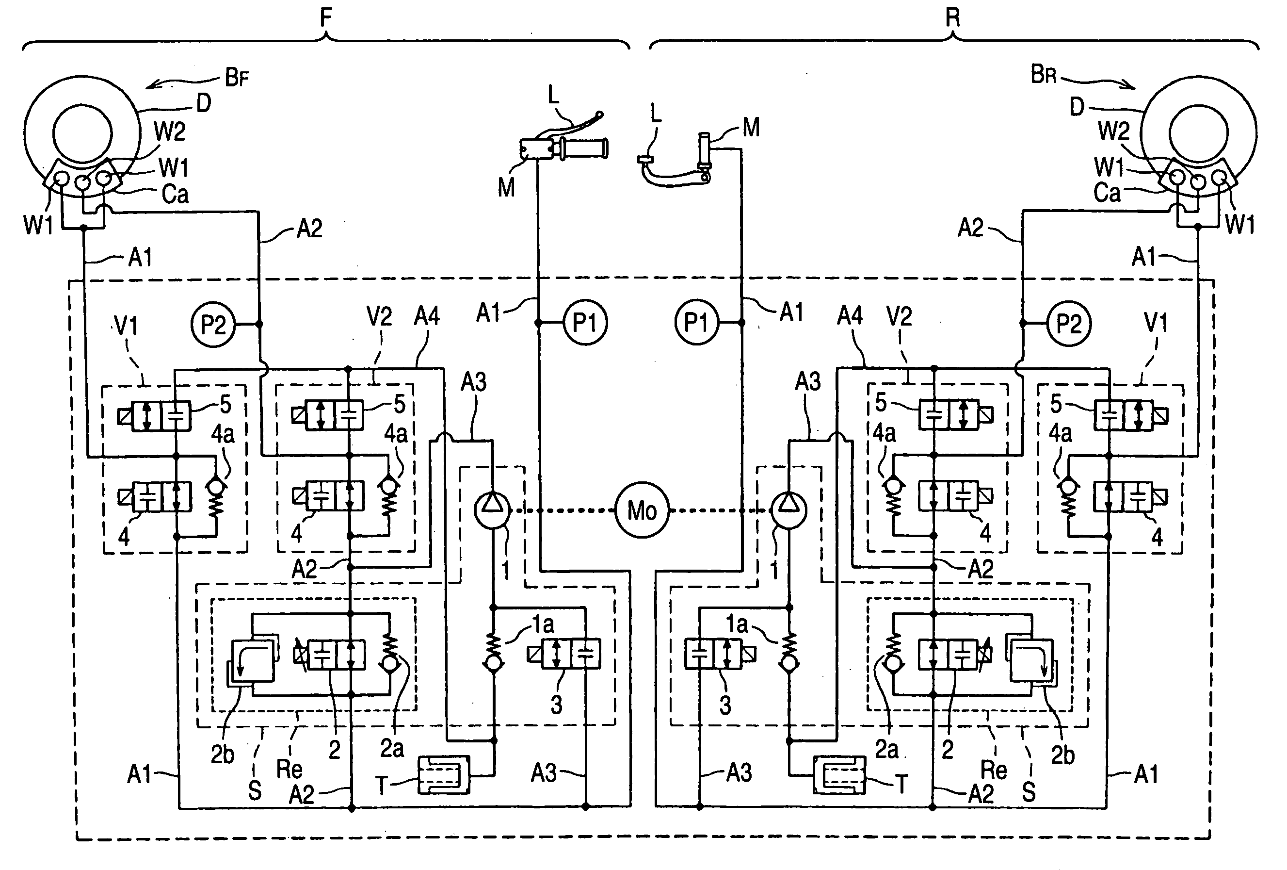
[0041]A brake fluid pressure control device for a bar handle vehicle of an embodiment of the invention is suitably used for a bar handle-type vehicle such as a two-wheeled motor vehicle, a three-wheeled motor vehicle, and an all terrain vehicle (ATV) As shown in FIG. 1, this brake fluid pressure control device for a bar handle vehicle is comprised of a brake system F for a front wheel which imparts a braking force to a front wheel brake BF, a brake system R for a rear wheel which imparts a braking force to a rear wheel brake BR, and an unillustrated control unit for executing such as interlocked brake control for interlocking the both brakes BF and BR and antilock brake control of the both brakes BF and BR.

[0042]Since in this embodiment the hydraulic circuits of the both brake systems F and R are identical, a description will be given hereafter mainly of the front wheel brake system F, and the brake system R for the rear wheel will be described, as required.

[0043]The front wheel bra...


PUM


Abstract

A brake fluid pressure control device for a bar handle vehicle has a front wheel brake system which imparts a braking force to a front wheel and a rear wheel brake system which imparts a braking force to a rear wheel. At least one of the brake systems has a master cylinder which generates brake fluid pressure in accordance with an operation amount of a brake operation element, first and second wheel cylinders both of which impart the brake force on one of the front and rear wheels, a first hydraulic path which communicates the master cylinder with the first wheel cylinder, a second hydraulic path which is branched from the first hydraulic path and connected to the second wheel cylinder and a boosting unit which boosts the brake fluid pressure in the second wheel cylinder without boosting the brake fluid pressure in the first wheel cylinder.

Description

BACKGROUND OF THE INVENTION[0001]1. Field of the Invention[0002]The present invention relates to a brake fluid pressure control device for a bar handle vehicle.[0003]2. Description of Related Art[0004]As a hydraulic circuit of a brake fluid pressure control device which is mainly used for a bar handle-type vehicle (hereafter simply referred to as the “bar handle vehicle”), such as a two-wheeled motor vehicle, a three-wheeled motor vehicle, and an all terrain vehicle (ATV), one is known which is capable of effecting a brake control in which wheel brakes for front and rear wheels are interlocked (hereafter referred to as interlocked brake control), in addition to antilock brake control for each wheel brake (e.g., refer to Japanese Patent Unexamined Publications JP-A-2000-71963 and JP-A-2007-69906).[0005]The known hydraulic circuit has a brake system for braking one of the front and rear wheel brakes (e.g., the rear wheel brake) and a brake system for braking the other wheel brake (e.g...

Claims


Application Information

Patent Timeline
Patent Type & Authority Applications(United States)
IPC IPC(8): B60T8/44F16D65/18
CPCB60T8/1706B60T8/261B60T8/3225B60T8/3275B60T2201/06B60T8/4072B60T8/442B60T8/4872B60T2201/03B60T8/345
Inventor NAKAMURA, MOTOYASUHAMANAKA, TAKAYUKI
Owner HITACHI ASTEMO LTD
Learn More