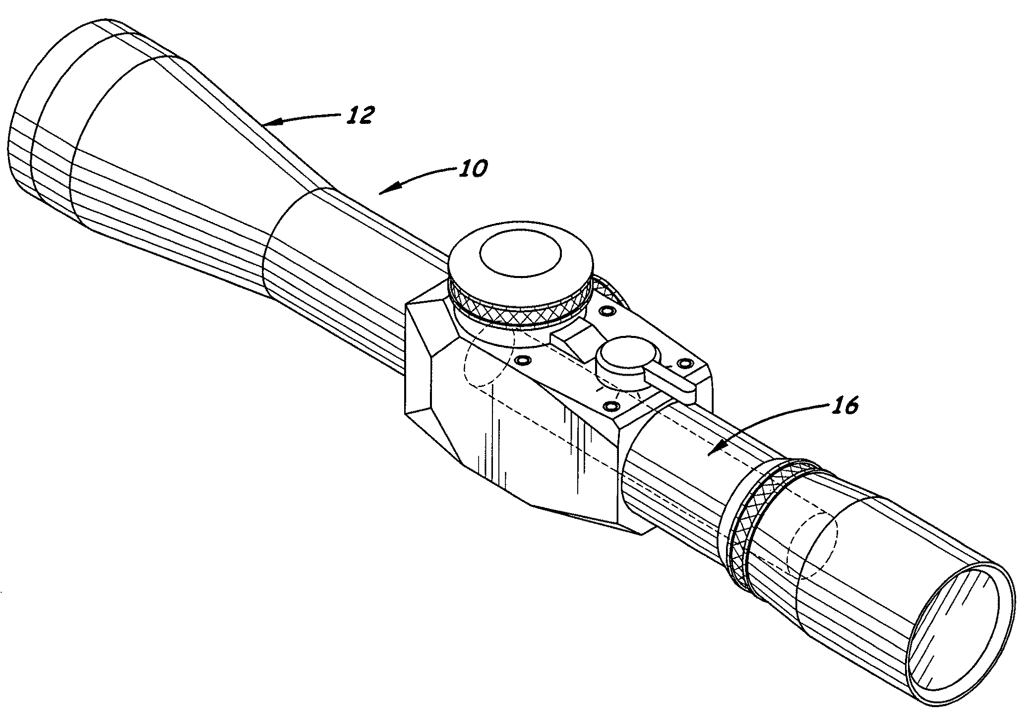
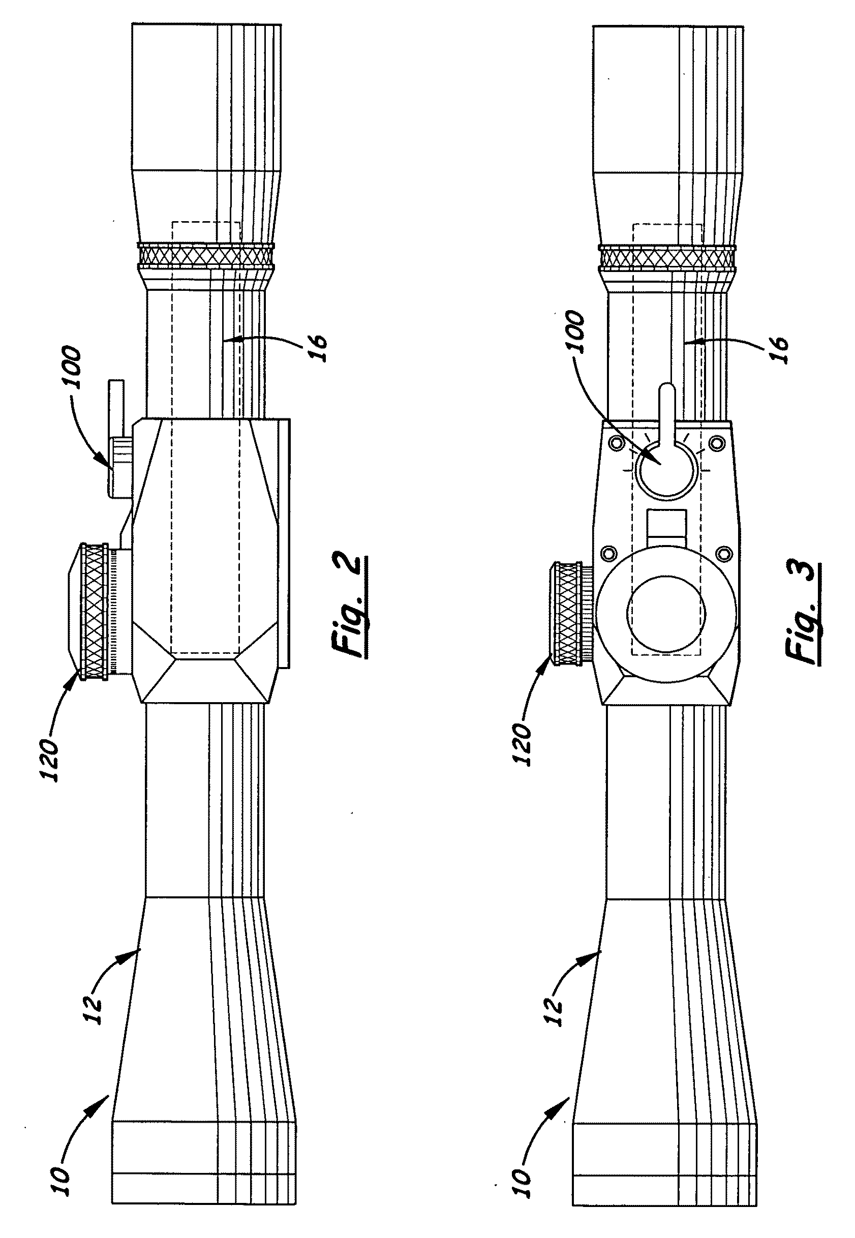
Riflescope High Speed Adjusting Elevation Assembly
a technology of elevation adjustment and riflescope, which is applied in the field of riflescopes, can solve the problems of slow and confusing situation, limited total amount of elevation movement per rotation of adjustment, and slow engagement time with the targ
- Summary
- Abstract
- Description
- Claims
- Application Information
AI Technical Summary
Benefits of technology
Problems solved by technology
Method used
Image
Examples
first embodiment
[0030]In the first embodiment, shown in FIGS. 4-6, the adjustment plate is a flex plate 20 affixed along its front edge to the mounting surface 18. The flex plate 20 includes a flat plate 21 with a transversely aligned groove 23 formed on its lower surface. The groove 23 enables the rear section of the flex plate 20 to bend upward when an upward force is exerted on the rear section 24 of the flex plate 20. The flex plate 20 is slightly beveled so that when the front section 22 of the flex plate 20 is attached to the mounting surface 18, the rear section 24 is slightly elevated above the mounting surface 18. One or more optional springs 60 are disposed between the rear section 24 and the mounting surface 18 to bias the rear section 24 upward.
[0031]The rotating post member 40 includes a top jam nut 42, an upper bearing support 44 and a lower bearing support 48. Located between the upper bearing support 44 and the top surface of the flex plate 20 is an upper bearing 46A. Located betwee...
second embodiment
[0032]In a second embodiment, shown in FIGS. 7-9, the flex plate 20 is replaced with a hinge plate 20′. The hinge plate 20′ is affixed along its front section to a transversely aligned hinge pin 22′ attaching it to the hinge joint 25′ located in front of the hinge plate 20′. The hinge joint 25′ is securely attached to the cover plate 70 located above the hinge plate 20′ with two screws 29′ allowing the hinge plate 20′ to “float” in the mounting surface 18 after assembly. In the preferred embodiment, the hinge plate 20′ has a flat thick front section and a thinner rear section 26′ allowing the mounting of the cam follower ball 28. When the front section of the hinge plate 20′ is pinned to the hinge joint 25′ and attached to the cover plate 70, the cam follower ball 28 rests against cam face 108 discussed further below.
[0033]One or more optional springs 60′ are disposed between the rear section of the hinge plate 20′ and the mounting surface 18. The springs 60′ bias and help hold the ...
PUM
 Abstract
Description
Claims
Application Information
 - R&D
- Intellectual Property
- Life Sciences
- Materials
- Tech Scout
- Unparalleled Data Quality
- Higher Quality Content
- 60% Fewer Hallucinations
Browse by: Latest US Patents, China's latest patents, Technical Efficacy Thesaurus, Application Domain, Technology Topic, Popular Technical Reports.
© 2025 PatSnap. All rights reserved.Legal|Privacy policy|Modern Slavery Act Transparency Statement|Sitemap|About US| Contact US: help@patsnap.com


