
Control circuit and camera apparatus

Inactive Publication Date: 2009-08-06
SONY CORP
View PDF11 Cites 12 Cited by
  • Summary
  • Abstract
  • Description
  • Claims
  • Application Information

AI Technical Summary

Benefits of technology

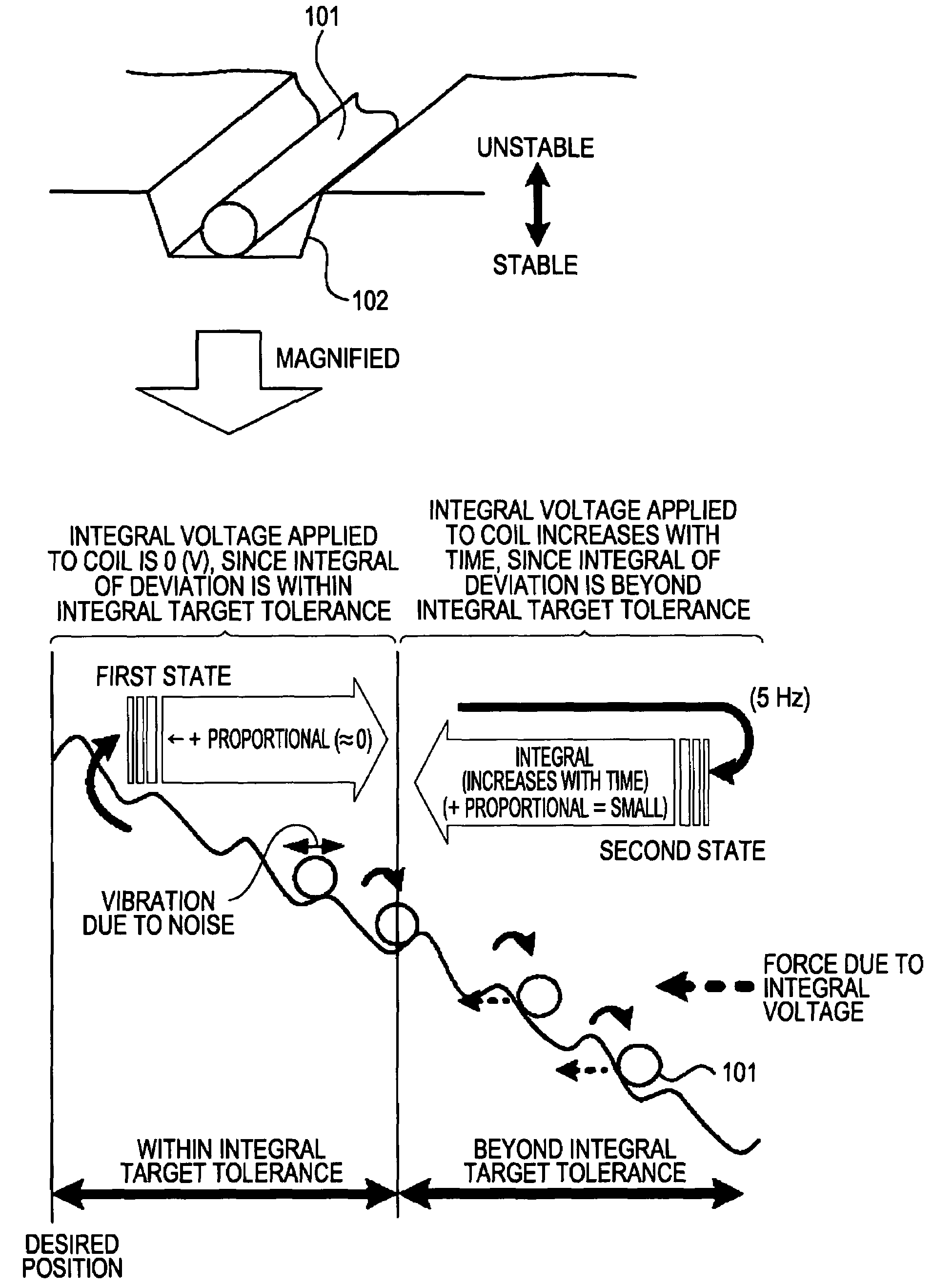
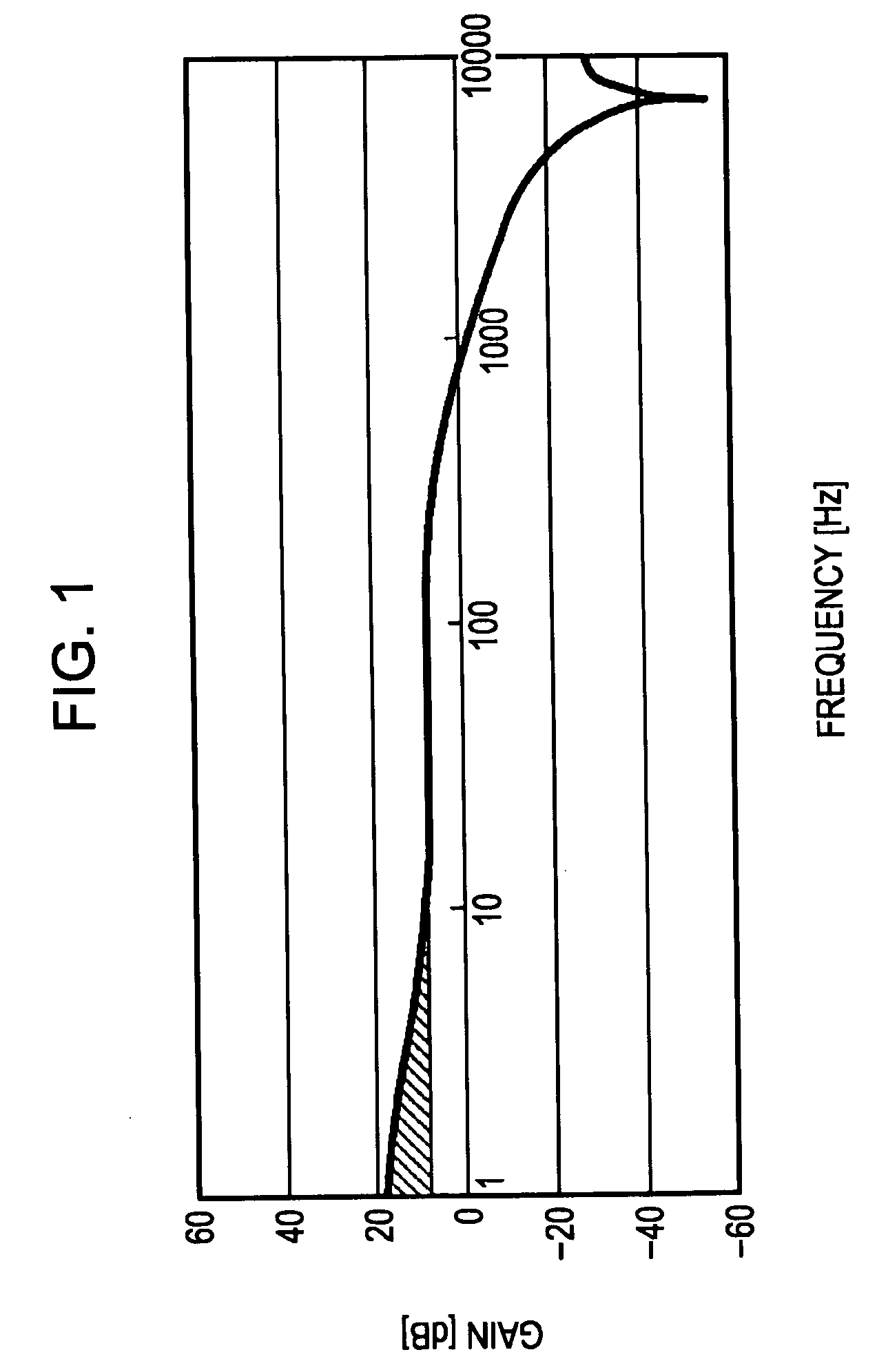
[0018]According to an embodiment of the invention, the integral gain ki of the control parameters is set to be in a range from 0.1 to 4200, and a gain in the low frequency region of frequency characteristics is improved.
[0019]As described above, according to an embodiment of the invention, it is possible to realize a stable control system in which a slow oscillation is suppressed in a low-frequency region, in a light-load control system for objects such as an iris or an ND filter, by appropriately setting parameters such as an integral gain.

Problems solved by technology

Generally, a large loop gain, while allowing high-speed control of an object, will cause large overshoot and oscillation of the feedback control system, making the system unstable.
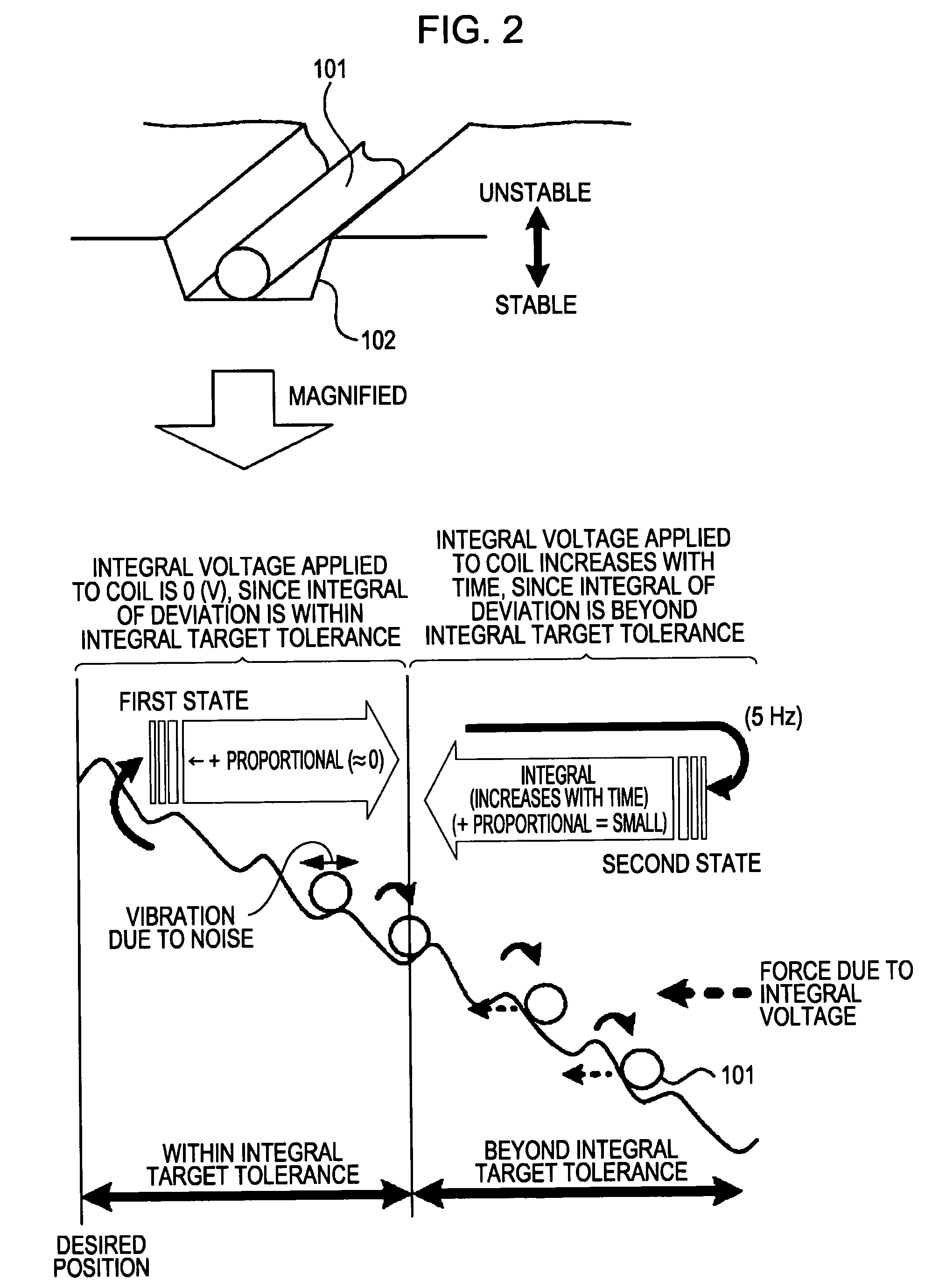
On the other hand, a small loop gain, while making the system stable, results in a longer time before the system becomes stable and causes so-called stick-slip motion.
This phenomenon, when it occurs during control of an iris or an ND filter, causes an unfavorable stepwise change in the amount of light projected onto an image pickup element.
The insufficient gain in such a low-frequency region causes several problems regarding friction, such as image fluctuation (jitter) and a stick-slip phenomenon, i.e., the amount of light projected onto an image pickup element unfavorably changes stepwise.
These problems are observed especially in a light-load control object such as an iris or an ND filter.

Method used


Image

  • Control circuit and camera apparatus
  • Control circuit and camera apparatus
  • Control circuit and camera apparatus

Examples


Embodiment Construction

[0029]An exemplary embodiment according to the invention will be described below with reference to the accompanying drawings.

[0030]Embodiments described below are specific preferred examples of embodiments for implementing the invention, and hence include several technically desirable restrictions. However, the description of embodiments below does not limit the invention to the embodiments unless otherwise stated. Therefore, for example, materials and the amounts used, process times, the order of processes, numerical conditions of parameters described below, and the like are merely desirable examples. Furthermore, the dimensions, shapes, and positional relationships in the drawings, for example, are also merely examples and are schematically illustrated.

[0031]FIGS. 3A and 3B show schematic structures of a camera apparatus according to an embodiment. FIG. 3A shows a state in which an iris aperture is made to be small, and FIG. 3B shows a state in which the iris aperture is made to b...


PUM


Abstract

A control circuit includes a desired value arithmetic unit that calculates a desired value of a control object, a sensor that detects a value indicating a state of an actuator used to displace the control object, a deviation arithmetic unit that calculates a deviation of the control object from the desired value, a proportional arithmetic unit that produces a proportional-component drive signal, an integral arithmetic unit that calculates an integral value of the deviation and produces an integral-component drive signal, a derivative arithmetic unit that calculates a derivative value of the deviation and produces a derivative-component drive signal, and a drive-signal output unit that outputs the drive signals provided from the integral arithmetic unit, the proportional arithmetic unit, and the derivative arithmetic unit to a drive circuit for the actuator. At least the integral gain ki of the integral arithmetic unit is in a range 0.1 V / rad·s≦ki≦4200 V / rad·s.

Description

CROSS REFERENCES TO RELATED APPLICATIONS[0001]The present invention contains subject matter related to Japanese Patent Application JP 2008-025665 filed in the Japanese Patent Office on Feb. 5, 2008, the entire contents of which are incorporated herein by reference.BACKGROUND OF THE INVENTION[0002]1. Field of the Invention[0003]The present invention relates to a control circuit that is suitable for application to light-load control of, for example, an iris and a neutral density (ND) filter for a camcorder and a still camera, and to a camera apparatus.[0004]2. Description of the Related Art[0005]In recent years, VCR integrated video cameras and still cameras (collectively called cameras) have been reduced in size and weight in accordance with an increase in the density with which their various components are packaged. In line with this trend of reduction in size and weight of cameras, image pickup devices have also been reduced in size and weight. Examples of such devices include an i...

Claims


Application Information

Patent Timeline
IPC IPC(8): G05B13/02
CPCG05B11/42
Inventor KITAGAWA, KOJI
Owner SONY CORP
Learn More