
Axle drive unit for a hybrid electric vehicle

a hybrid electric vehicle and drive unit technology, applied in the direction of motor/generator/converter stopper, dynamo-electric converter control, gearing, etc., can solve problems such as packaging difficulties for the vehicle designer, and achieve the effect of reducing the speed of elements, compact positioning of mechanical drive elements, and simplifying bearing support requirements

Active Publication Date: 2009-08-06
FORD GLOBAL TECH LLC
View PDF22 Cites 64 Cited by
  • Summary
  • Abstract
  • Description
  • Claims
  • Application Information

AI Technical Summary

Benefits of technology

[0009]A torque reaction for the speed reduction planetary gearing is provided on a housing through a bore of a shaft or drum rather than through an outer diameter of the housing, thereby simplifying the bearing support requirements and allowing compact positioning of the mechanical drive elements.
[0010]Use of planetary gearing to reduce the speed of elements driven by the electric machine in the electric only drive path reduces the size of the package space required for the drive unit.

Problems solved by technology

Such electric hybrid drive systems, however, present packaging difficulties to the vehicle designer, particularly when layshaft gearing is used to transmit power from a longitudinal drive shaft to a rear axle.

Method used


Image

  • Axle drive unit for a hybrid electric vehicle
  • Axle drive unit for a hybrid electric vehicle
  • Axle drive unit for a hybrid electric vehicle

Examples


Embodiment Construction

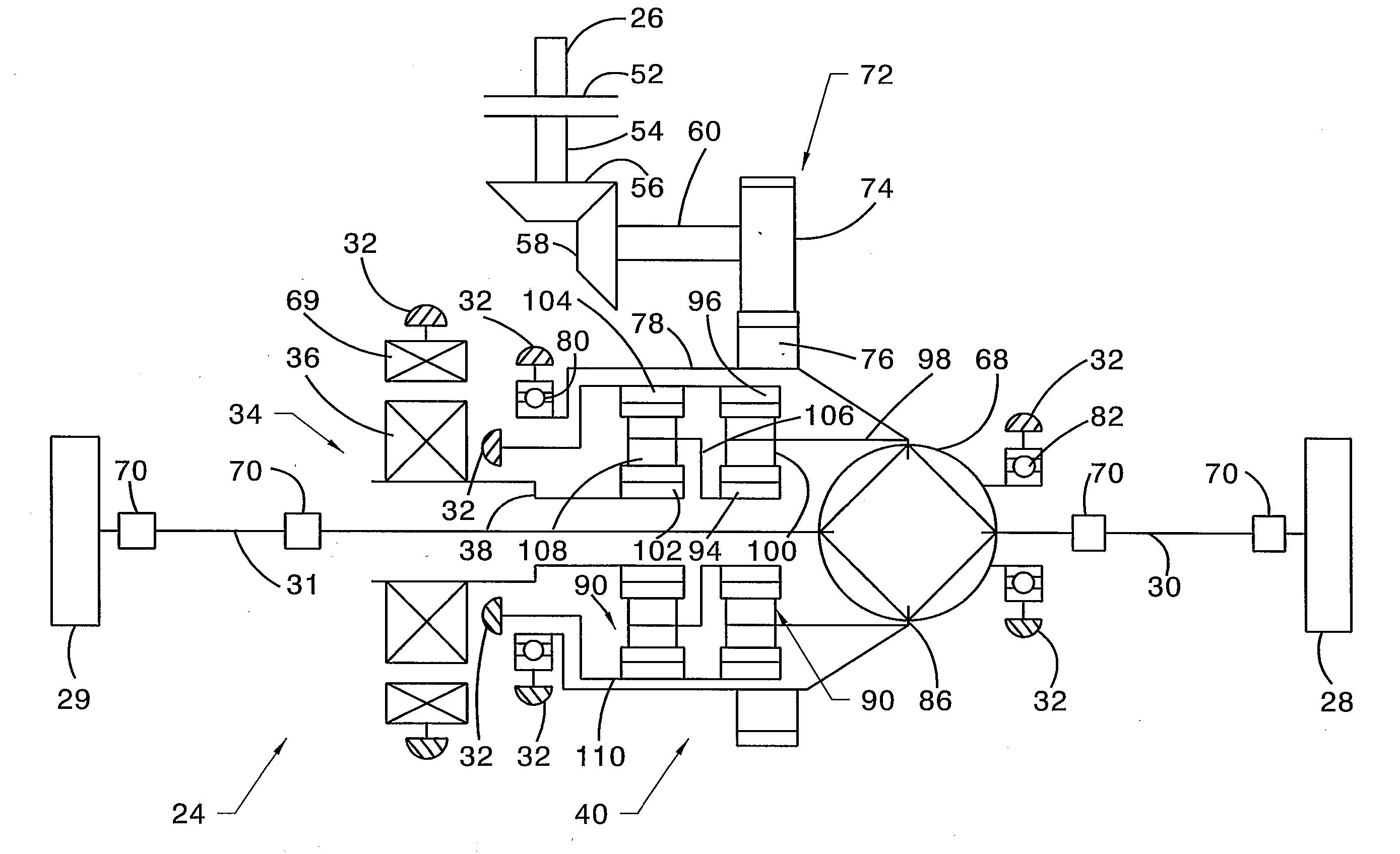
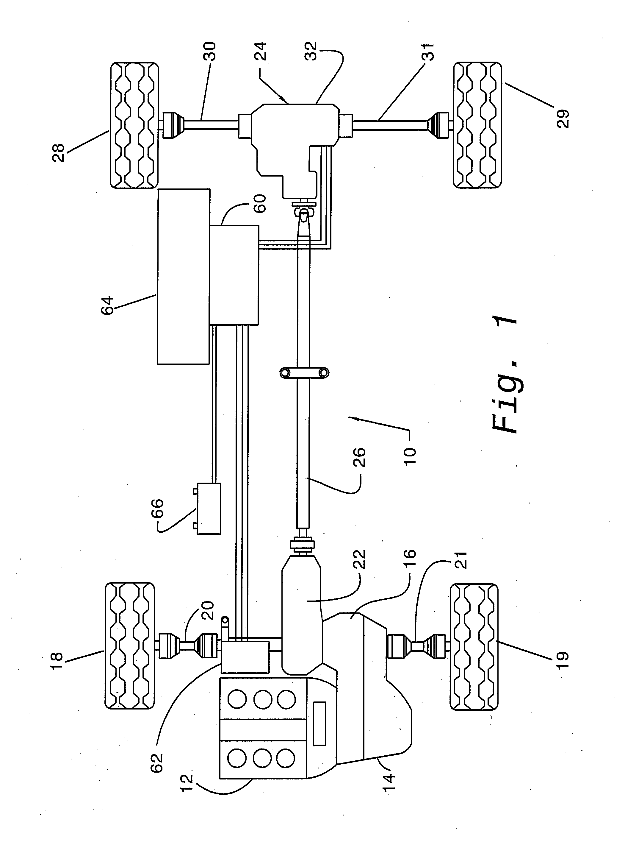
[0016]The powertrain 10 for a hybrid electric motor vehicle illustrated in FIG. 1 includes an IC engine 12, a transmission 14, which drives a front final drive unit 16 connected to a pair of front wheels 18, 19 by front drive shafts 20, 21. Transmission 14 may be a manual gearbox or any type of automatic transmission. The front final drive unit 16 also drives a rear drive take-off unit 22, which is connected to a rear final drive unit 24, i.e., the ERAD unit, by a longitudinal prop shaft 26. The ERAD unit 24 is driveably connected to a pair of rear wheels 28, 29 by rear drive shafts 30, 31. The ERAD unit 24 includes a casing 32, which contains the inboard ends of the rear drive shafts 30, 31.

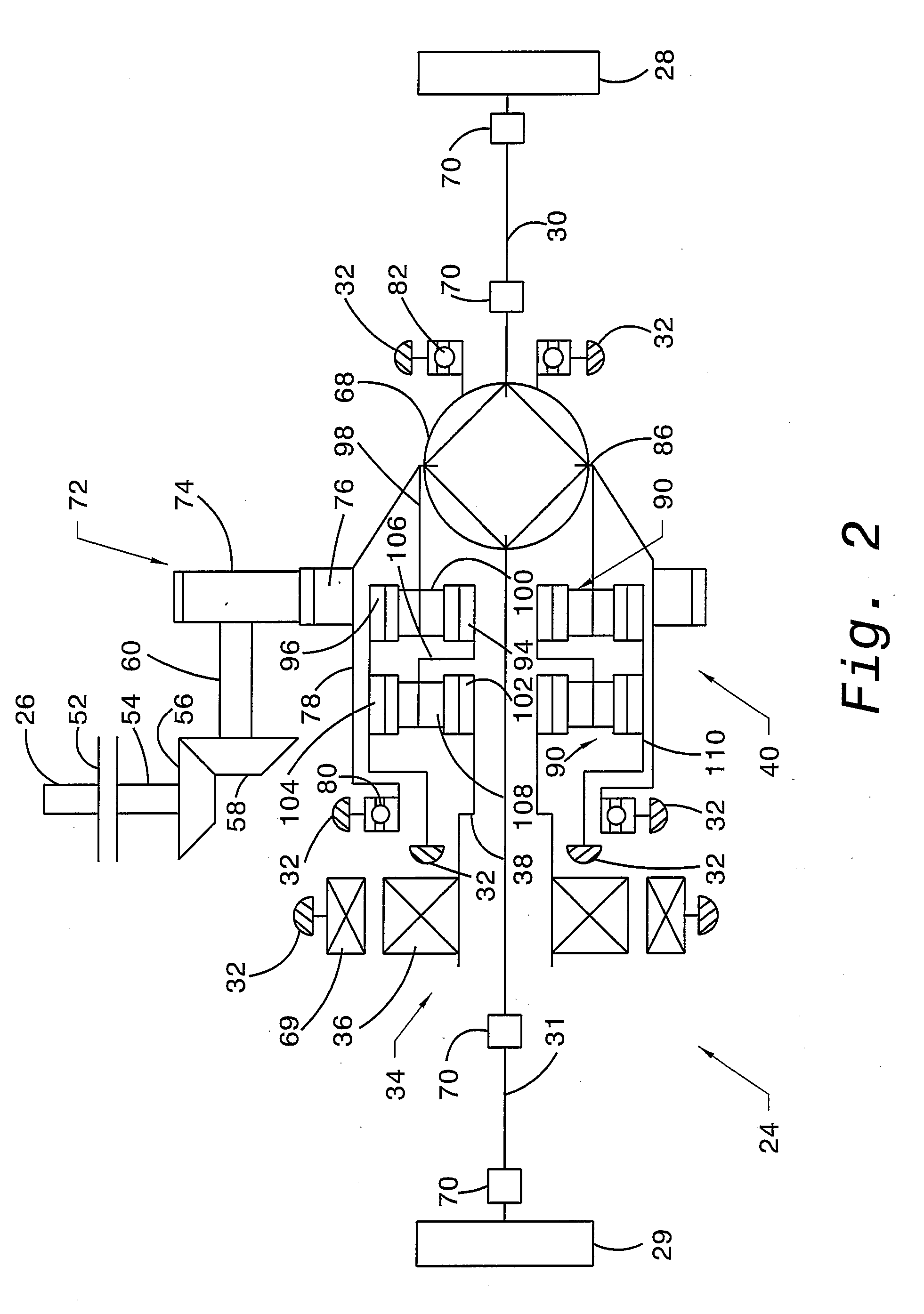
[0017]FIG. 2 shows an electric machine 34, such as a motor / generator, arranged transversely in the ERAD unit 24. The electric machine 34 includes a hollow rotor 36, which is connected by a sleeve shaft 38 to a speed reduction planetary gear unit 40.

[0018]A clutch or coupler 52 alternately opens ...


PUM


Abstract

A drive unit for a hybrid electric motor vehicle includes an engine, an electric machine including a rotor, a layshaft gearset including an input driveably connected to the engine and an output, for transmitting power between the input and the output and producing a first speed differential that causes a speed of the input to exceed a speed of the output, first and second driveshafts, a differential mechanism driveably connected to said output, for transmitting power between said output and the driveshafts, and a planetary gear unit driveably connected to the output and the rotor, for transmitting power between said rotor and said output and producing a second speed differential that causes a speed of the rotor to exceed the speed of the output.

Description

BACKGROUND OF THE INVENTION[0001]1. Field of the Invention[0002]This invention relates generally to a powertrain for a vehicle, and, more particularly, to a powertrain having multiple power sources including an electric motor for driving a set of vehicle wheels.[0003]2. Description of the Prior Art[0004]Hybrid electric powertrains have been developed that include an electric motor and an internal combustion (IC) engine, which can operate independently or in combination depending on the driving conditions, the state of charge of a traction battery, and the power source that most efficiently meets the current power demands imposed by the vehicle operator.[0005]Most electric hybrid vehicles available commercially are front wheel drive vehicles, in which only the front wheels are driven. Hybrid electric powertrains being developed for use in four-wheel drive vehicles allow both the motor and engine to transmit power to a rear set of driven wheels.[0006]When packaging an electric motor d...

Claims


Application Information

Patent Timeline
IPC IPC(8): F16H37/08B60K6/20F16H3/72F16H48/08F16H3/62H02P3/00
CPCB60K6/365B60K6/48B60K6/485B60K6/52Y02T10/6265F16H48/36F16H2048/364Y02T10/6221Y02T10/6226F16H48/08Y10S903/903Y02T10/62
Inventor JANSON, DAVID A.
Owner FORD GLOBAL TECH LLC
Learn More