
Hand-held device and method for detecting concealed weapons and hidden objects

a technology of concealed weapons and hand-held devices, applied in the field of detection, can solve problems such as exposing the user to a potentially hazardous and unanticipated situation, chemical explosives, and detection devices based on electromagnetic waves cannot detect plastic or ceramic weapons, and achieve the effect of improving the uniformity of reflection

Inactive Publication Date: 2009-08-06
ARIEL UNIV RES & DEV
View PDF22 Cites 102 Cited by
  • Summary
  • Abstract
  • Description
  • Claims
  • Application Information

AI Technical Summary

Benefits of technology

[0025]In one embodiment of the detection device of the invention, the pulses of millimeter waves are generated at two or more distinct frequencies, thereby improving the uniformity of the reflection from the whole of the target.

Problems solved by technology

While the passage device is precluded for use at lower risk checkpoints due to its cost and complexity, the use of the hand-held detection device necessitates a user to come in bodily contact with the person being examined, thereby exposing the user to a potentially hazardous and unanticipated situation, such as when the person being examined is found to be a suicide bomber.
However, these systems have some significant limitations:A detection device based on electromagnetic waves cannot detect plastic or ceramic weapons, chemical explosives, or narcotics;A detection device based on X-ray and acoustic waves is efficacious only if it is deployed in relatively close proximity to an object of investigation;A detection device based on optical and IR systems cannot identify concealed objects, such as those that are screened by clothes, fabric, paper, cardboard, and some building materials.
Although these detection devices may provide high quality imaging, they are costly, particularly due to the need of an expensive scanner and positioning system, or of a large number of receivers defining a focal plane array when functioning as independent pixels.
The time needed for image reconstruction with these prior art detection devices is excessively long at regions of high congestion of bystanders or pedestrians.
Due to the recent rise in global security problems and terror, security personnel urgently need an inexpensive, hand-held and easy to operate detection device that can be used in regions of high congestion of bystanders or pedestrians such as at the entrance of a train station, school, shopping mall, sports stadium or cinema, or on board a bus whereat a stationary passage device is not practical.
This detection device suffers from several deficiencies.
Consequently, specific locations of a suspect such as the arms or legs cannot be accurately detected due to the lack of spatial resolution.
Thirdly, a complicated software algorithm is required to process the output with respect to the frequency of each pulse.
Additionally, a considerably more expensive receiver, more expensive by a factor of approximately 10, would be needed if the weapon detection system of U.S. Pat. No. 6,359,582 were adapted to transmit and receive millimeter-wave radiation, resulting in an unaffordable detection device.

Method used


Image

  • Hand-held device and method for detecting concealed weapons and hidden objects
  • Hand-held device and method for detecting concealed weapons and hidden objects
  • Hand-held device and method for detecting concealed weapons and hidden objects

Examples


example

[0084]In order to check the feasibility of using the detection device of the invention to distinguish between different types of materials the maximum voltage of the reflected signal from various target objects made of different metallic and non-metallic materials and having different shapes were tested. The measurements were made using standard conditions, i.e. distance, strength of transmitted signals, frequency, etc.

[0085]A 20-L plastic container filled with tap water served as a simulation of a human body. Since a combination of the human body and a plastic carton, in which a potentially dangerous object is concealed, is commonly found during detection operations, such a combination was simulated by placing test objects having a height of 25 cm containing different types of concealed material such as plastic, cardboard, Teflon, ceramic, cheese, and soap, in front of the plastic container. A Shottky detector was positioned at a distance of 1 m from a test object irradiated by mil...


PUM


Abstract

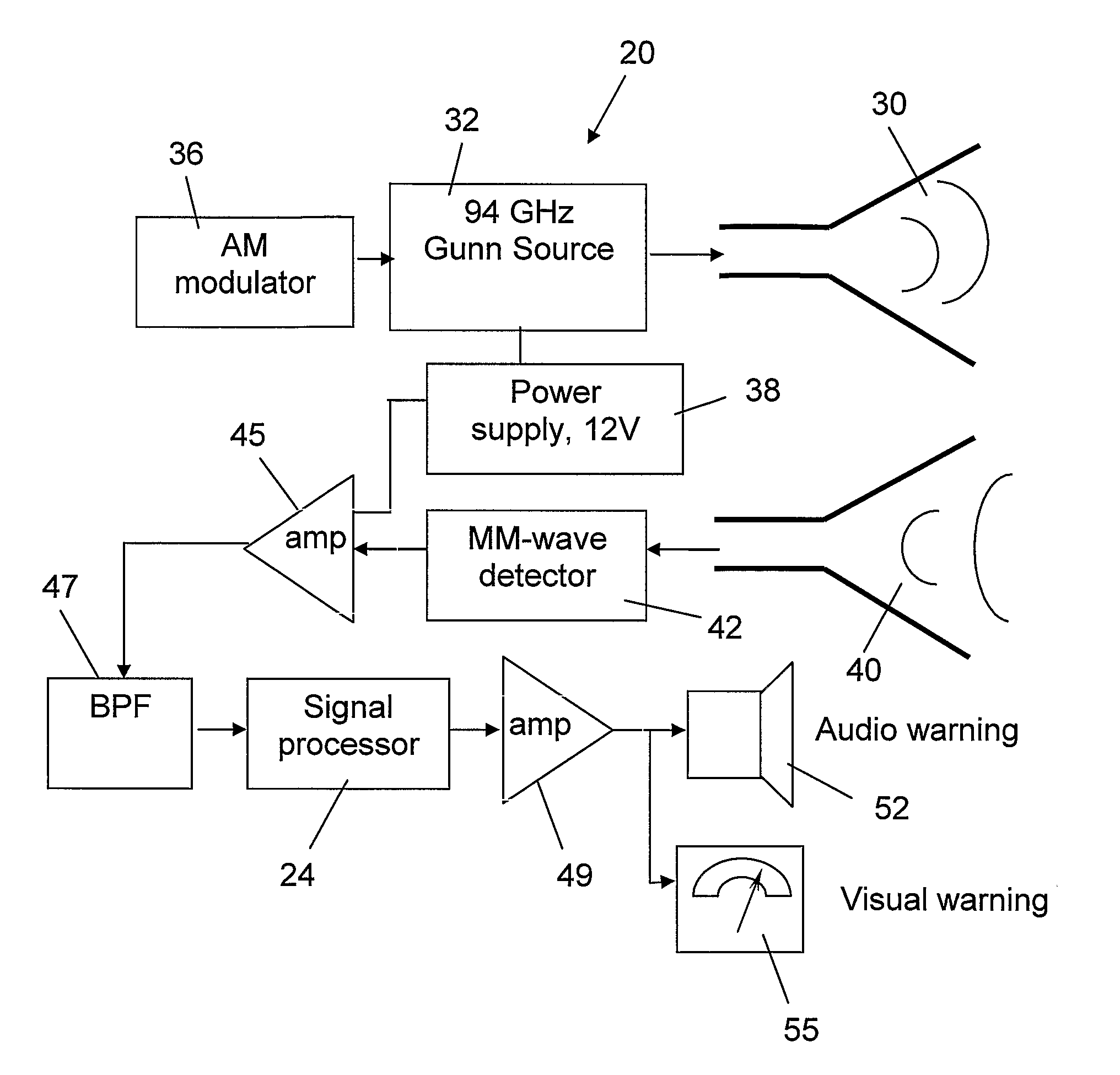
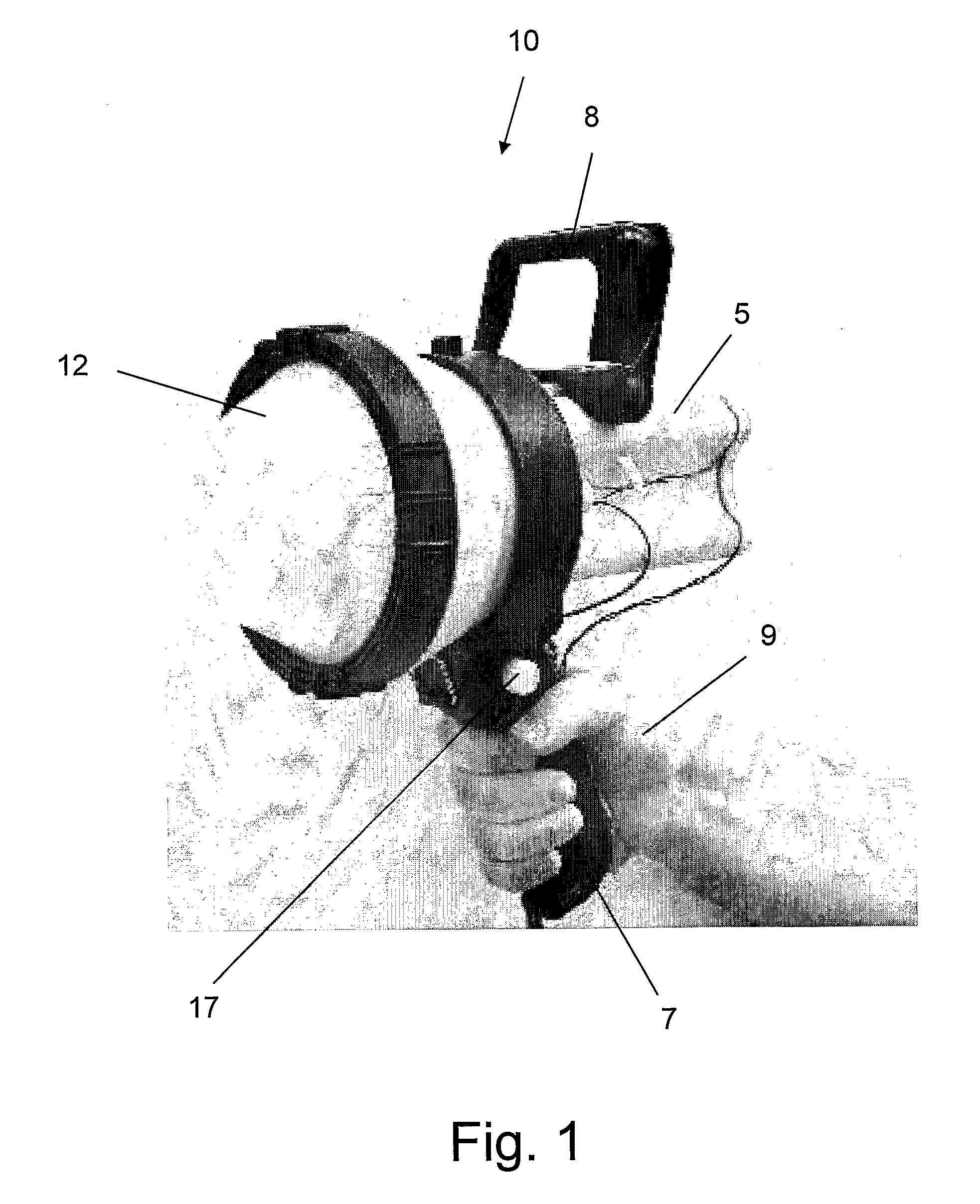
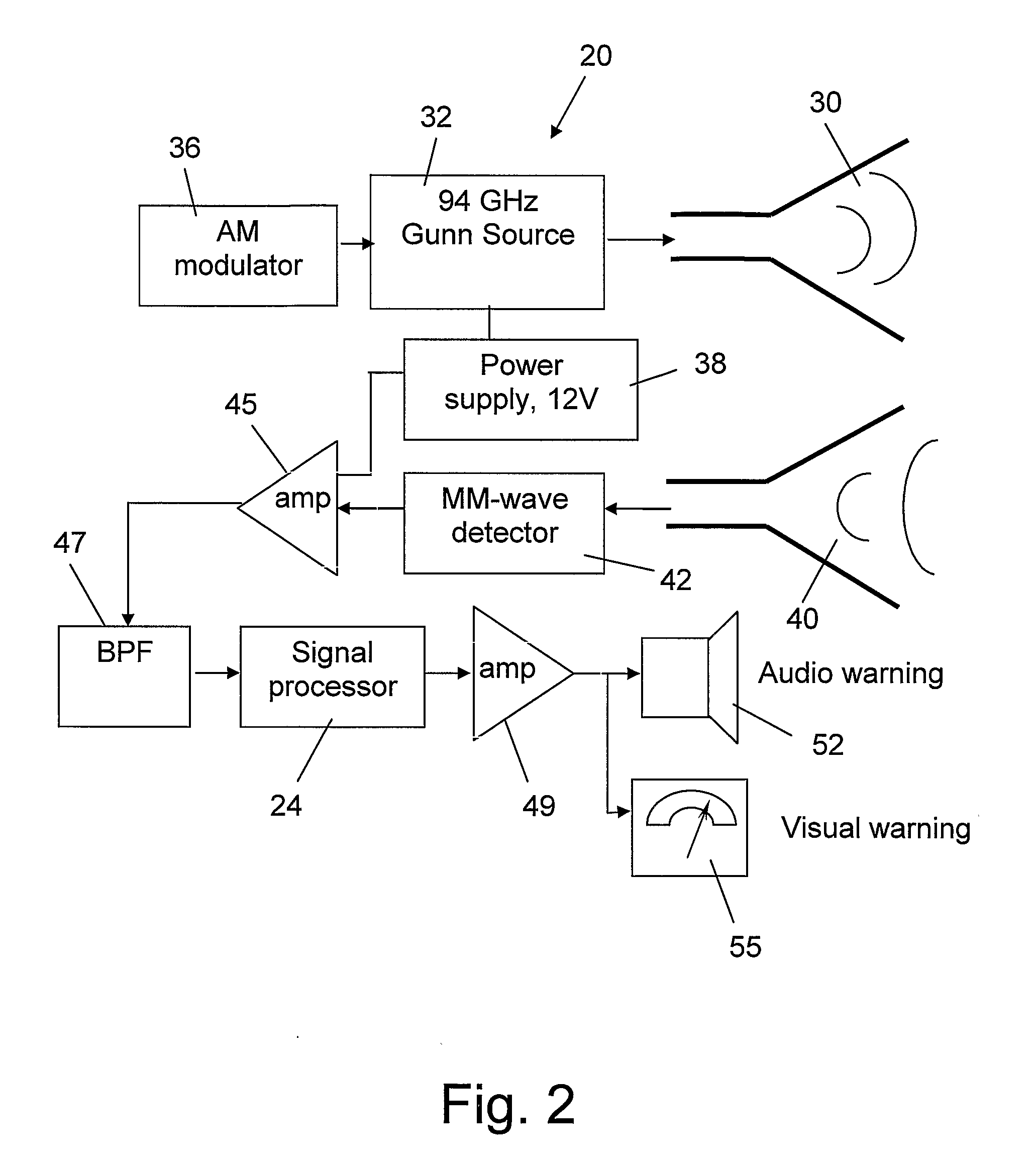
The present invention is an inexpensive, hand-held, and easy to operate millimeter-wave detection device that employs a non-imaging sensor which radiates a pulse of millimeter waves of a certain amplitude and frequency towards a target located at a distance from the detection device. The sensor receives pulses of millimeter waves that are reflected from the target and generates a voltage waveform that is characteristic mainly of the target material, while other parameters such as distance to the target are known. The processor of the detection device measures both the peak voltage and the rate of increase of the voltage until it reaches the maximum. Using an algorithm stored in a software module, the deviation between the rate of the voltage rise and the peak voltage is compared with values of similar parameters for a number of test targets made of different materials that were previously collected and stored in a calibration table in the memory of the device. A concealed object, e.g. a weapon, is positively identified when the measured voltage rise is found to be similar to one of the stored voltage rises. The circuitry of the detection device generates a visual and / or audio output to a display device which is indicative to the operator as to whether a concealed object is present and, if a match is found with the data in the calibration table, the nature of the concealed object is also displayed. In addition to the basic mode of operation described, various other operation modes can be employed with the detection device of the invention.

Description

FIELD OF THE INVENTION[0001]The present invention relates to the field of detectors. More particularly, the invention relates to a device for detecting concealed weapons and various hidden objects by using a millimeter wavelength generator and detector.BACKGROUND OF THE INVENTION[0002]The most prevalent device for detecting concealed weapons and metallic hidden objects is the magnetic metal detector. A stationary passage device, through which a person being examined walks, employs a metal detector and is deployed at portals such as airports, embassies, and other high risk checkpoints. A simple hand-held device is used at lower risk checkpoints, such as a mall entrance. While the passage device is precluded for use at lower risk checkpoints due to its cost and complexity, the use of the hand-held detection device necessitates a user to come in bodily contact with the person being examined, thereby exposing the user to a potentially hazardous and unanticipated situation, such as when ...

Claims


Application Information

Patent Timeline
Patent Type & Authority Applications(United States)
IPC IPC(8): G01S7/41G01S13/00
CPCG01S7/032G01V8/005G01S13/04G01S7/412
Inventor KAPILEVICH, BORISEINAT, MOSHE
Owner ARIEL UNIV RES & DEV
Learn More