
Combined chiller and boiler HVAC system in a single outdoor operating unit

a chiller and boiler technology, applied in the direction of fluid heaters, lighting and heating apparatus, heating types, etc., can solve the problems of noisy forced air systems, inability to deliver simultaneous heating or cooling to selected areas, and total loss of energy required to create warm or cold air

Inactive Publication Date: 2009-07-30
SCHARING MICHAEL G +1
View PDF9 Cites 39 Cited by
  • Summary
  • Abstract
  • Description
  • Claims
  • Application Information

AI Technical Summary

Benefits of technology

[0016]Another object of the invention is to save space and create flexibility in building design by eliminating soffits and ductwork associated with forced air distribution systems.
[0018]Another object of the invention is to minimize the distribution of mold, dry rot and similar airborne health hazards created by forced air ducted systems.
[0019]Another object of the invention is to remove a fire hazard and a potential source of carbon monoxide by relocating the boiler to the outside of a building without compromising heating and cooling performance.
[0020]Another object of the invention is to eliminate the need for exhaust stacks used by boilers installed inside a building, by relocating the boiler to the outside of the building.
[0027]The invention is factory assembled and 100% tested prior to shipment offering singular reliability, installation, and maintenance advantages.

Problems solved by technology

Current forced air equipment cannot deliver simultaneous heating or cooling to selected areas where they serve the same structure.
Furthermore, once a forced air system shuts off after satisfying the demand, all warm or cold air in the ducts dissipates with no thermal retention and thus, the energy required to create warm or cold air is completely lost.
Forced air systems are noisy and by the nature of their operation, spread dust, mold and germs throughout a building.
All boilers present a certain risk of explosion when improperly installed or poorly maintained.
There are no small chillers that combine water and air cooling methods.
This is a costly and time consuming process.

Method used


Image

  • Combined chiller and boiler HVAC system in a single outdoor operating unit
  • Combined chiller and boiler HVAC system in a single outdoor operating unit
  • Combined chiller and boiler HVAC system in a single outdoor operating unit

Examples


Embodiment Construction

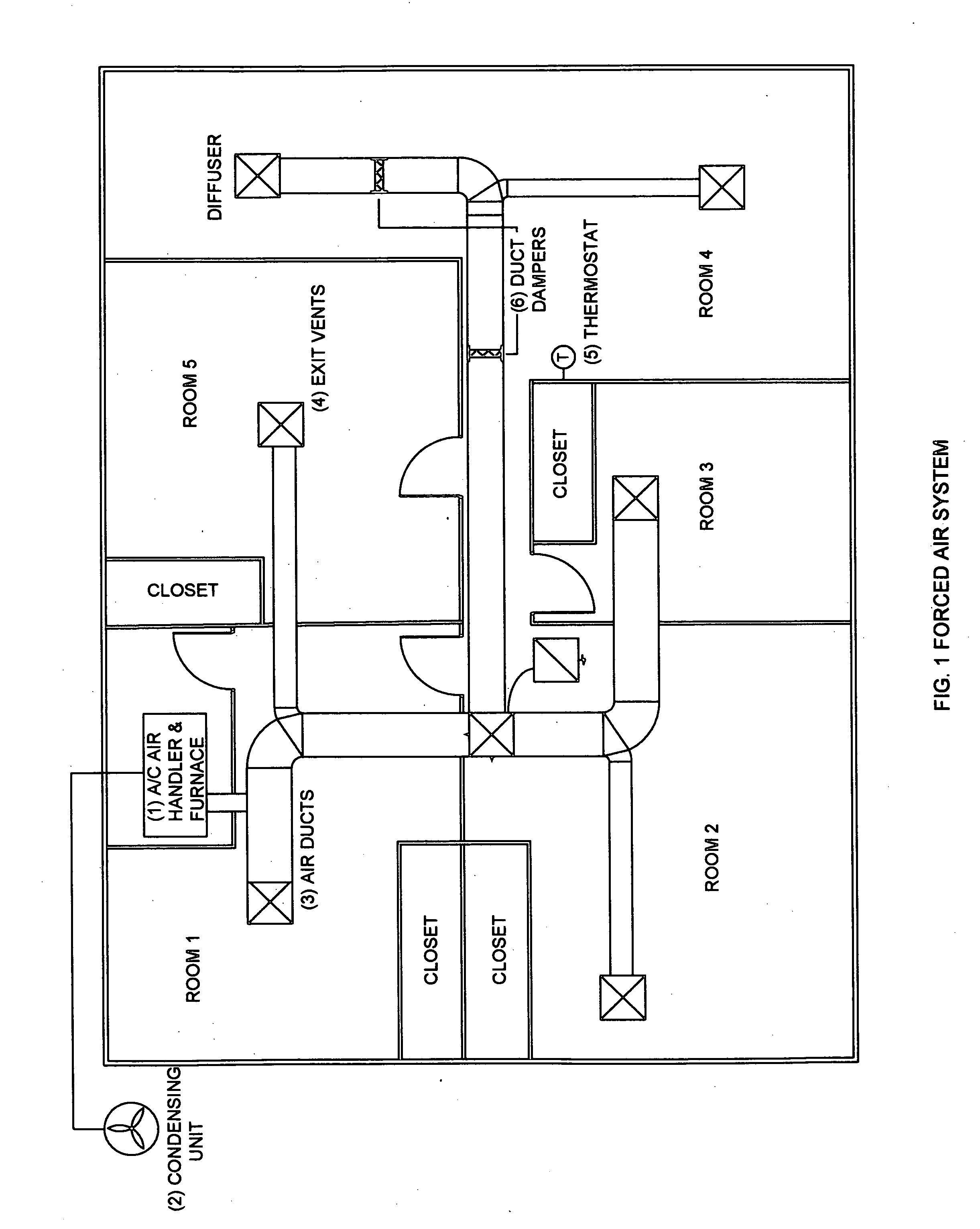
[0034]FIG. 1 shows a typical forced air system employing a heating unit furnace (1) installed in the building and the air conditioning condenser (2) portion of the air conditioning system installed a the exterior of the building. Either heated or cooled air can be selected to be delivered throughout the building via a series of ducts (3) to adjustable exit vents (4) located in the individual rooms in the building. FIG. 1 illustration is a small version of a forced air system however anyone knowledgeable in the state of the art knows that in larger structures there is simply more extensive duct work and larger capacity units. Typically, one thermostat (5) controls the entire system.

[0035]In more complex forced air systems where greater control of temperature gradients is required, the ducting may be further divided into zones which can be manually or electronically adjusted, or programmed to operate automatically, utilizing duct dampers (6) driven by additional thermostats. It must b...


PUM


Abstract

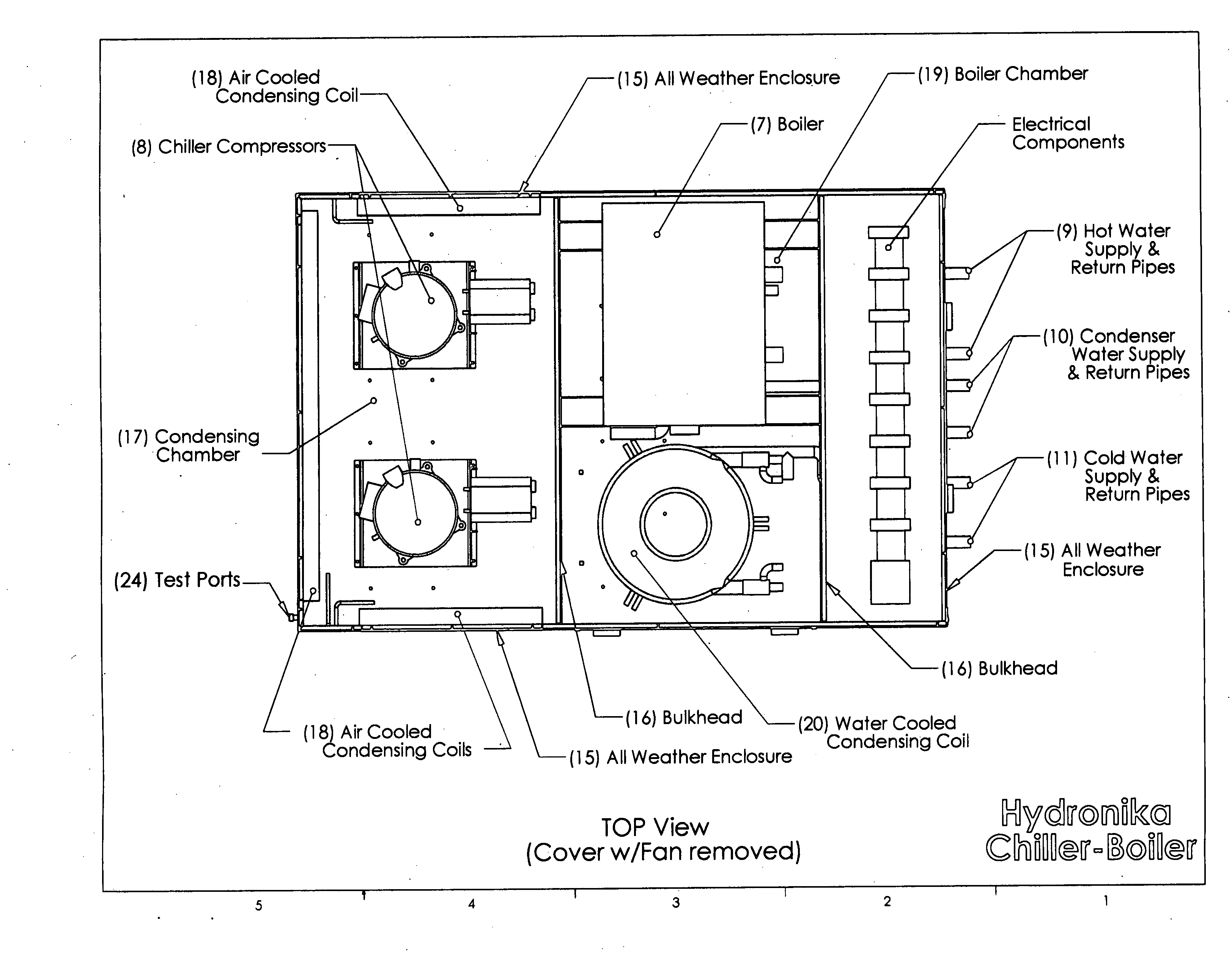
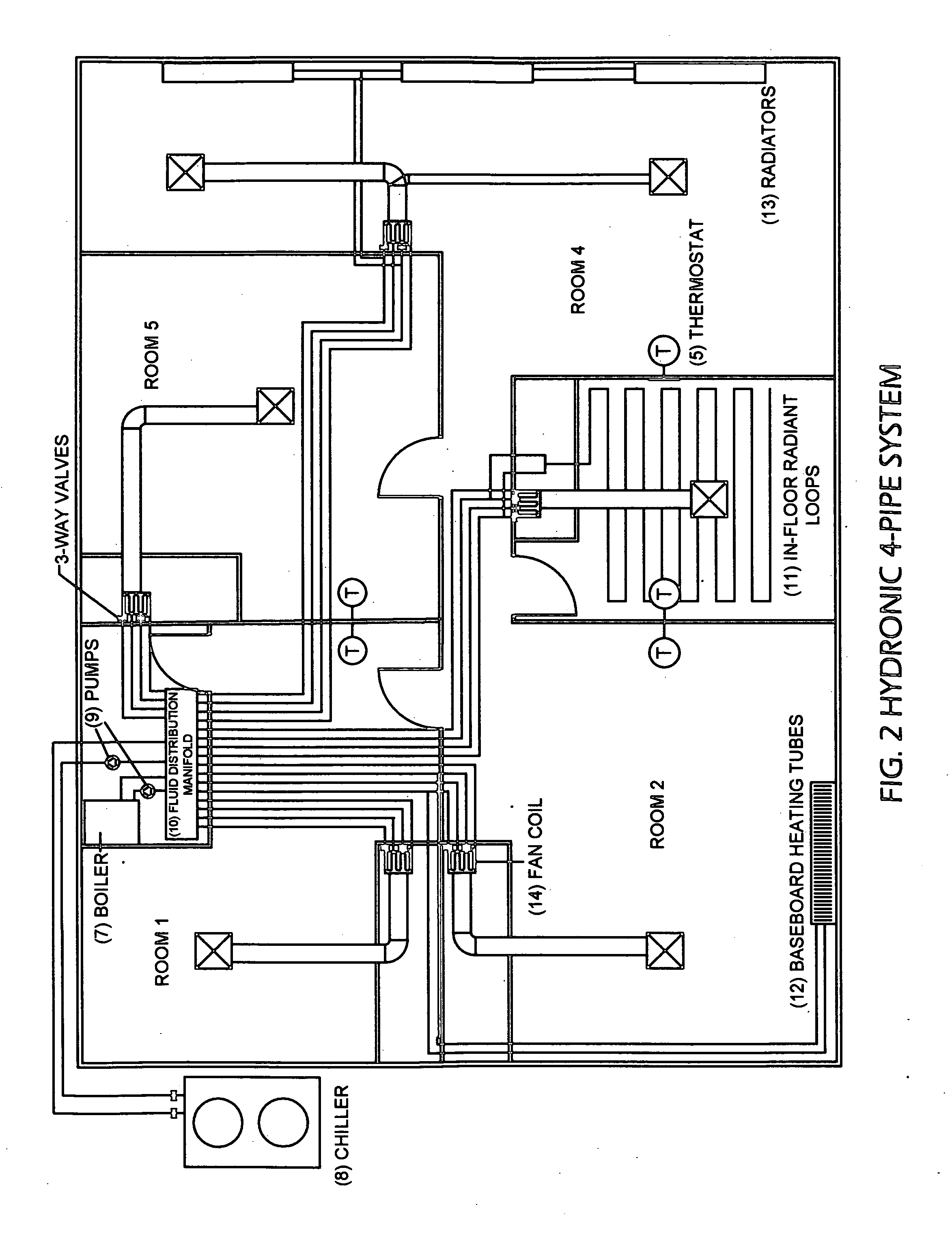
A combined chiller-boiler HVAC system which integrates all operating components including the boiler, chiller, distribution pumps, condenser coils, condenser fans and controls onto one single enclosed platform built for installation exterior to the structure being served and designed to produce heated or cooling fluid sequentially or simultaneously in differing areas of a building on demand. This system utilizes both air and water cooling whereby waste heat absorbed during a water cooling cycle, can be captured and re-directed for other uses.

Description

[0001]No federally sponsored research and development association exists with this invention. As such, there are no rights associated therewith.BACKGROUND OF THE INVENTION[0002]This invention is related to the methods used to supply heating and cooling to residential and commercial buildings which ordinarily require two separate systems, one for heating and another for cooling.[0003]Typical applications of heat and / or cooling within commercial and / or residential building provide either heating or cooling. There are numerous building configurations or “use” applications where it is desired or required to supply heat in one area and cooling in another. Medical-professional buildings, hospitals, computer rooms and large or multi storied residential housing frequently need selective heating and cooling, Current equipment utilizes a separate heat source and a separate cooling source. The heat source is placed inside the building and the cooling source is placed outside the building. Heat...

Claims


Application Information

Patent Timeline
IPC IPC(8): F24D5/00
CPCF24H4/04F24F3/06Y02P80/10
Inventor SCHARING, MICHAEL G.MILLBURN, COURTNEY R.
Owner SCHARING MICHAEL G
Learn More