Dual-power supplying system with circuit loop switching control circuit

a switching control and dual-power supply technology, applied in the direction of emergency power supply arrangements, relays, transportation and packaging, etc., can solve the problems of computer down, loss of hard disk data, power facility breakage, etc., and achieve the effect of low overall cost and large power consumption of the circuit of the present invention

Active Publication Date: 2009-07-23
TRENDON TOUCH TECHNOLOGY CORPORATION
View PDF27 Cites 25 Cited by
  • Summary
  • Abstract
  • Description
  • Claims
  • Application Information

AI Technical Summary

Benefits of technology

[0011]Thus, in view of the drawbacks and problems existing in the known automatically switchable dual-power-circuit-loop circuit system, an objective of the present invention is to provide an automatically switchable dual-power-circuit-loop circuit system that has a simple structure of circuit.
[0015]Compared to the known technology, the present invention uses a simple circuit loop switching control circuit to realize detection of the power supplying condition of a first power source circuit loop and to control the timing of supplying power from a second power source based on the detection. Thus, automatic switching of a dual power supply circuit can be realized without expensive power control ICs. Also, the circuit loop switching control circuit employed in the present invention does not include diodes that are used in the conventional technology, the drawbacks of large power consumption and generation of high temperature commonly observed in the conventional technology can be overcome in the present invention. Conclusively, the present invention uses simple circuit elements and control circuits to realize the switching control required in a dual power supply circuit and the overall cost for the circuit of the present invention is low.

Problems solved by technology

Damage caused by power failure includes computer down, loss of hard disk data, and break of power facility.
The consequence caused by power failure is in general very hard to remedy for business.
The previously described conventional circuit suffers the drawbacks of high power consumption and being easy to generate high temperatures in components thereof.
Since large currents are supplied through the diodes 43, 62, great amounts of power are consumed and problems of high temperature may be caused.
In this way, improved control and removal of the drawbacks of high power consumption and high temperature are achieved, but using power controlling means (including power transistor), which is generally of high expense, to substitute the simply-structured diode circuit makes the costs of the known circuit very high.

Method used


Image

  • Dual-power supplying system with circuit loop switching control circuit
  • Dual-power supplying system with circuit loop switching control circuit
  • Dual-power supplying system with circuit loop switching control circuit

Examples


first embodiment

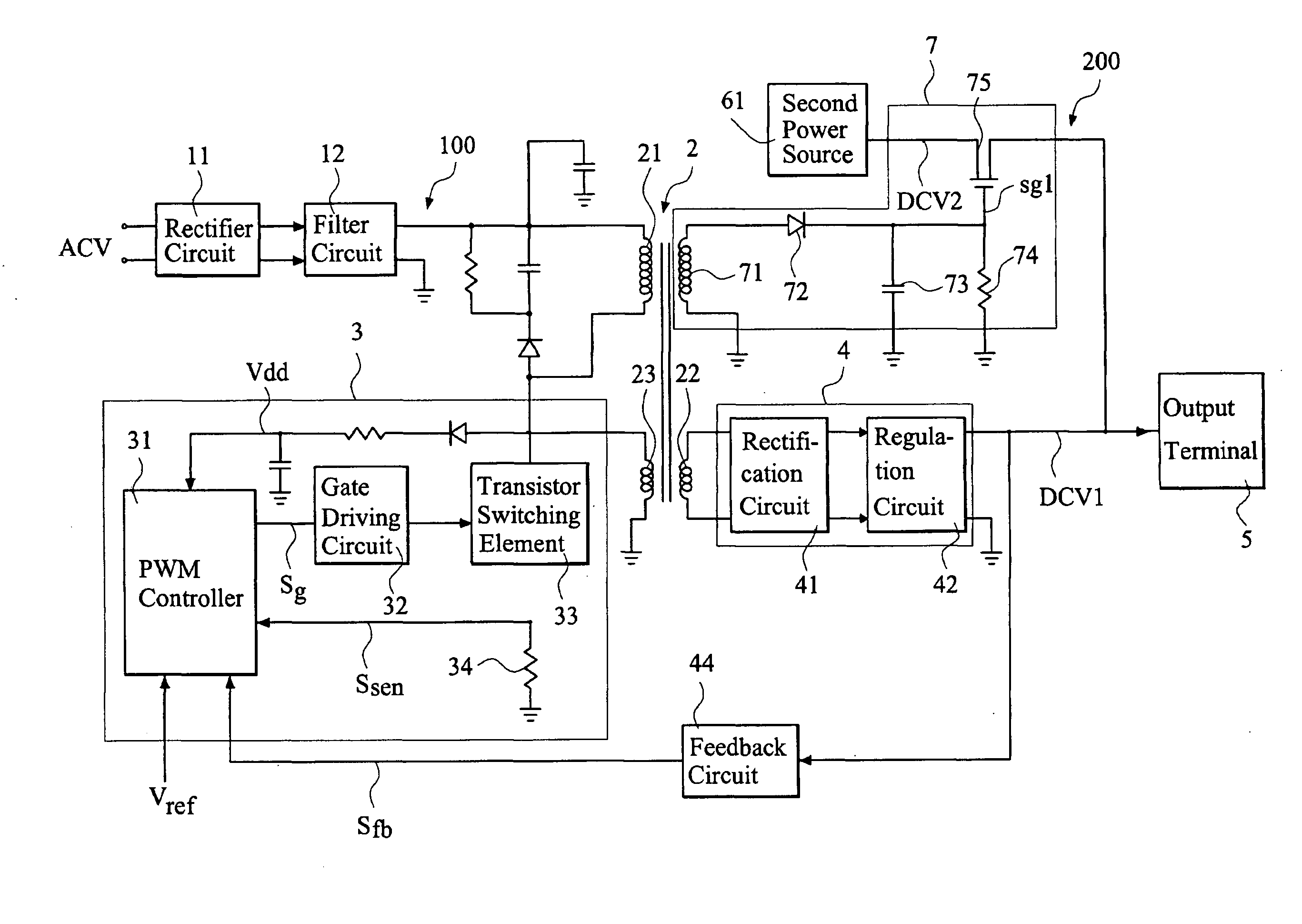
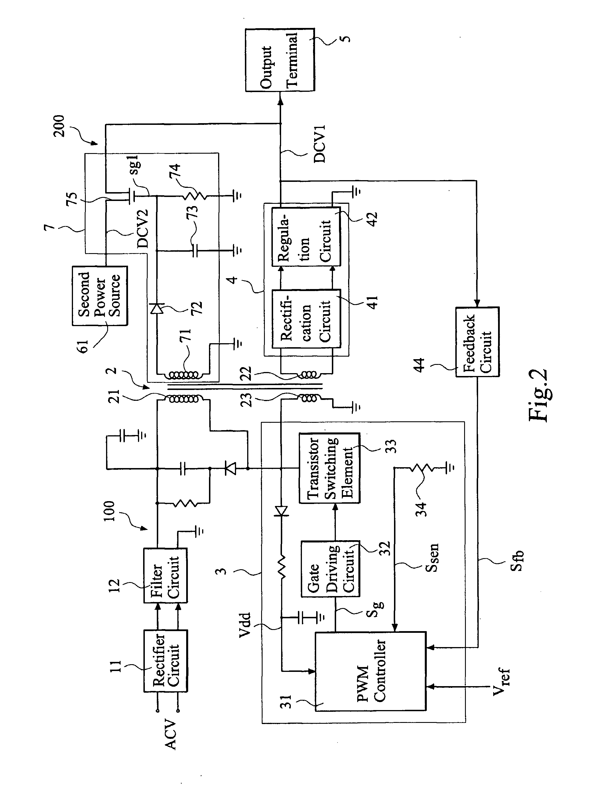
[0021]the present invention, as illustrated in FIG. 2, is applicable to a control system of a pulse-width-modulation (PWM) power converter that comprises an output transformer. When a first power source ACV is in normal operation to regularly supply electrical power, the first voltage output circuit loop 100 receives an operation voltage from the first power source ACV and supplies, in turn, a first output voltage DCV1 to a direct-current (DC) voltage output terminal 5. At this time, the second voltage output circuit loop 200 is cut off. On the other hand, when the first voltage output circuit loop 100 fails to supply the electrical power, the second voltage output circuit loop 200 takes over to supply a second output voltage DCV2 from a direct current (DC) power source (second power source) to the output terminal 5.

[0022]The first voltage output circuit loop 100 is generally comprised of a rectifier circuit 11, a filter circuit 12, an output transformer 2, a PWM control circuit 3, ...

second embodiment

[0030]FIG. 3 shows an automatically switchable dual-power-circuit-loop circuit system constructed in accordance with the present invention, which is applicable to a control system of a PWM power converter that comprises no output transformer.

[0031]In accordance with the second embodiment of FIG. 3, when a first power source ACV is in normal operation to regularly supply electrical power, a first voltage output circuit loop 100a receives an operation voltage from the first power source ACV and supplies, in turn, a first output voltage DCV1 to a DC voltage output terminal 5. At this time, a second voltage output circuit loop 200a is cut off. On the other hand, when the first voltage output circuit loop 100a fails to supply the first power source to the output terminal 5, the second voltage output circuit loop 200a takes over to supply a second output voltage DCV2 from a DC power source (second power source) to the output terminal 5.

[0032]The first voltage output circuit loop 100a is g...


PUM


Abstract

An automatically switchable dual-power-circuit-loop circuit system selectively supplies a first power source through a first voltage output circuit loop to an output terminal, and a second power source is selectively supplied through a second voltage output circuit loop to the output terminal. A switching control circuit functions to detect the first output voltage of the first voltage output circuit loop. When the first output voltage regularly supplies electrical power, the first power source is supplied through the first voltage output circuit loop to the output terminal, while the switching control circuit generates a switching signal to switch a switching element to an open-circuit condition thereby cutting off the second voltage output circuit loop. When the first power source fails to supply power, the switching element is set in a closed-circuit condition to allow the second power source to be supplied through the second voltage output circuit loop to the output terminal.

Description

FIELD OF THE INVENTION[0001]The present invention relates to an automatically switchable dual-power-circuit-loop circuit system, and in particular to a dual-power supplying system with a circuit loop switching control circuit.BACKGROUND OF THE INVENTION[0002]Stable supply of electrical power is getting more and more important for the high-tech era, and protection to business from damage caused by power failure is one of the key factors for the success of a high-tech company. Damage caused by power failure includes computer down, loss of hard disk data, and break of power facility. The consequence caused by power failure is in general very hard to remedy for business.[0003]To cope with the problem, an automatically switchable dual-power-circuit-loop circuit system is available in the market, which has a system architecture that is connected with two power sources of different voltage output circuit loops, such as an alternating current (AC) power source provided by electric main and ...

Claims


Application Information

Patent Timeline
Patent Type & Authority Applications(United States)
IPC IPC(8): H02J9/00H02J1/00
CPCH02J9/06H02J1/102H02M1/10H02J1/10H02J9/061H02J9/068
Inventor HWANG, YAU-SHI
Owner TRENDON TOUCH TECHNOLOGY CORPORATION
Why Eureka
Try Eureka