
Positive displacement pump

a pump and positive technology, applied in the direction of fluid removal, insulation, borehole/well accessories, etc., can solve the problem of accumulating liquid in the wellbore of a gas producing well,

Inactive Publication Date: 2009-07-23
BAKER HUGHES INC
View PDF16 Cites 36 Cited by
  • Summary
  • Abstract
  • Description
  • Claims
  • Application Information

AI Technical Summary

Problems solved by technology

Accumulated liquid in the wellbore of a gas producing well can be a problem since it can reduce or prevent gas flow into the well.

Method used

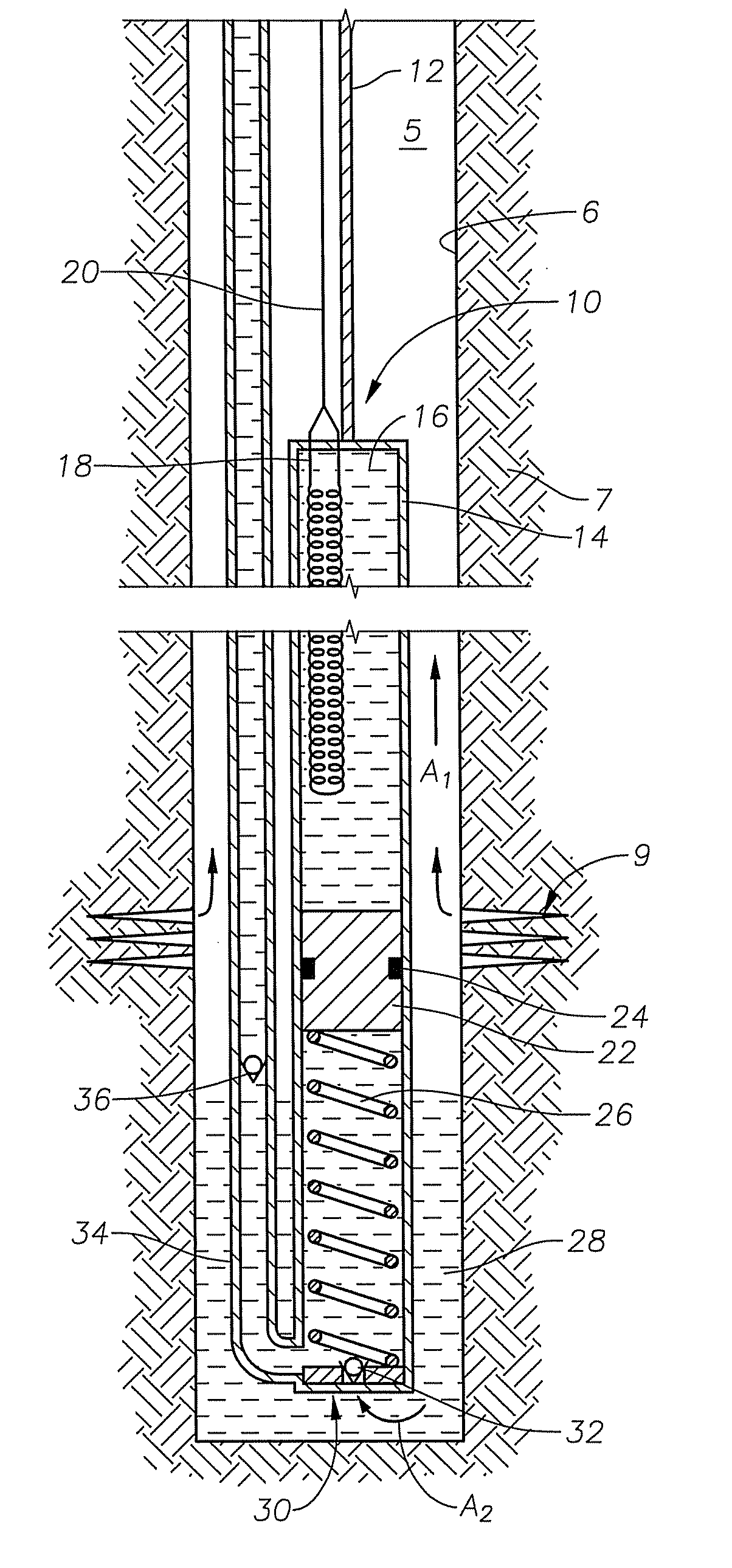
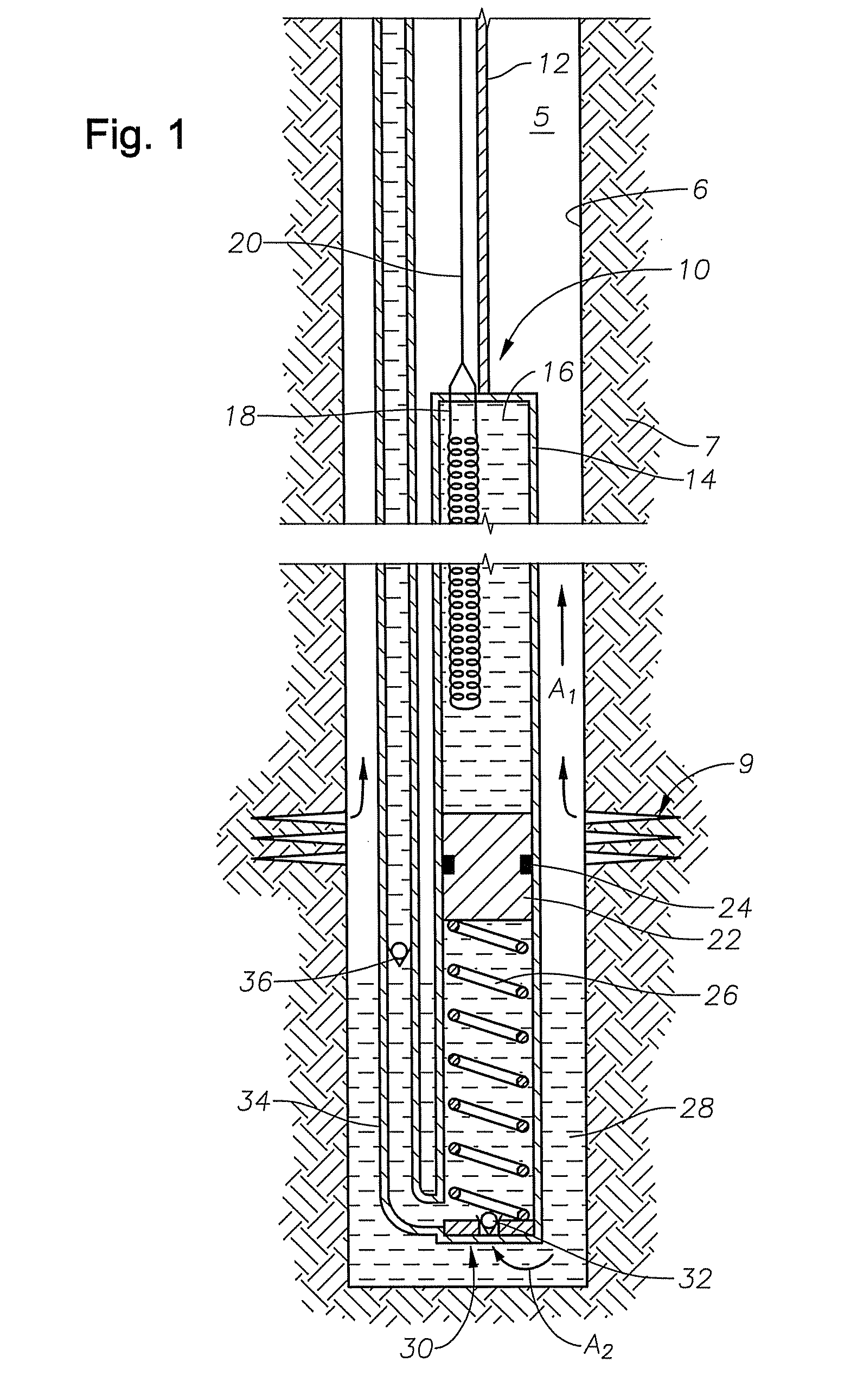
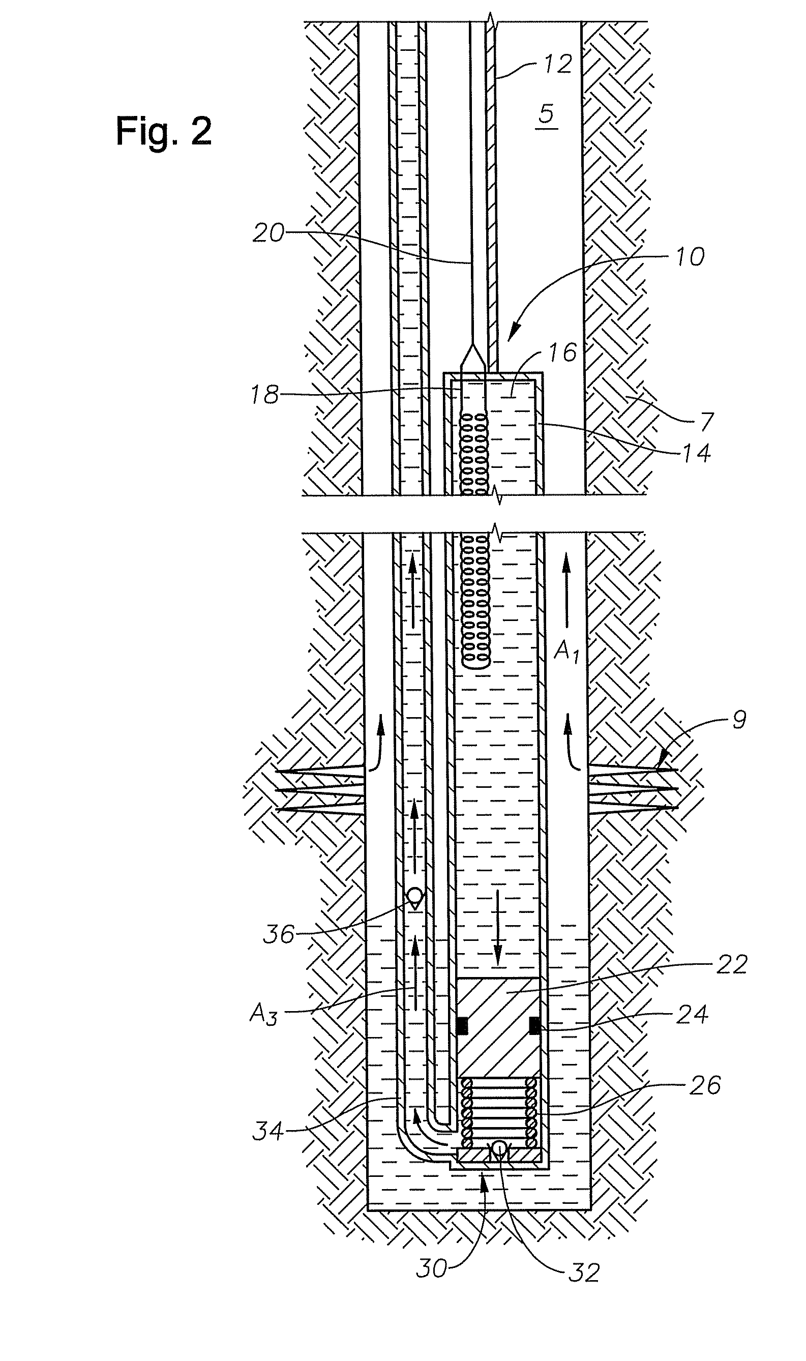

Image

  • Positive displacement pump
  • Positive displacement pump
  • Positive displacement pump

Examples


Embodiment Construction

[0014]The present invention will now be described more fully hereinafter with reference to the accompanying drawings in which embodiments of the invention are shown. This invention may, however, be embodied in many different forms and should not be construed as limited to the illustrated embodiments set forth herein; rather, these embodiments are provided so that this disclosure will be through and complete, and will fully convey the scope of the invention to those skilled in the art. Like numbers refer to like elements throughout.

[0015]The present disclosure provides embodiments of a downhole submersible pumping system for producing fluids from within a wellbore up to the surface. More specifically, the pumping system disclosed herein includes an expandable fluid that may expand in response to heating. The expandable fluid is contained within a housing adjacent a piston, where the piston is coaxially slidable within the housing. Thus expansion of the expandable fluid pushes against...


PUM


Abstract

A submersible pumping system for use downhole that includes a housing containing an expandable fluid, that when expanded pushes a piston that in turn pumps wellbore fluid to the surface. The expandable fluid can be a silicon based heat transfer fluid with a coefficient of thermal expansion of at least about 0.0005 in3 / in3 / ° F. The expandable fluid is expanded upon exposure to heat. A heat source is selectively activated for expanding the fluid.

Description

BACKGROUND[0001]1. Field of Invention[0002]The present disclosure relates to downhole pumping systems submersible in well bore fluids. More specifically, the present disclosure concerns a pumping system having a positive displacement pump where the pump reciprocatingly operates in response to expansion and contraction of an operating liquid.[0003]2. Description of Prior Art[0004]Submersible pumping systems are often used in hydrocarbon producing wells for pumping fluids from within the well bore to the surface. These fluids are generally liquids and include produced liquid hydrocarbon as well as water. One type of system used in this application employs a electrical submersible pump (ESP). ESPs are typically disposed at the end of a length of production tubing and have an electrically powered motor. Often, electrical power may be supplied to the pump motor via wireline.[0005]In many gas wells water (and possibly other liquids) is also produced with the gas. As the two-phase gas / liqu...

Claims


Application Information

Patent Timeline
IPC IPC(8): E21B36/04
CPCE21B43/121E21B36/04
Inventor COX, DON C.
Owner BAKER HUGHES INC
Learn More