
Displacement Control Valve

a technology of displacement control valve and displacement control, which is applied in the direction of positive displacement liquid engine, water supply installation, machines/engines, etc., can solve the problems of normal pressure control in the crank chamber, compressors that do not operate at a normal capacity, and cannot be enlarged, so as to reduce the manufacture minimize the operation cost of air conditioners

Active Publication Date: 2009-07-23
MAHLE INT GMBH +1
View PDF5 Cites 71 Cited by
  • Summary
  • Abstract
  • Description
  • Claims
  • Application Information

AI Technical Summary

Benefits of technology

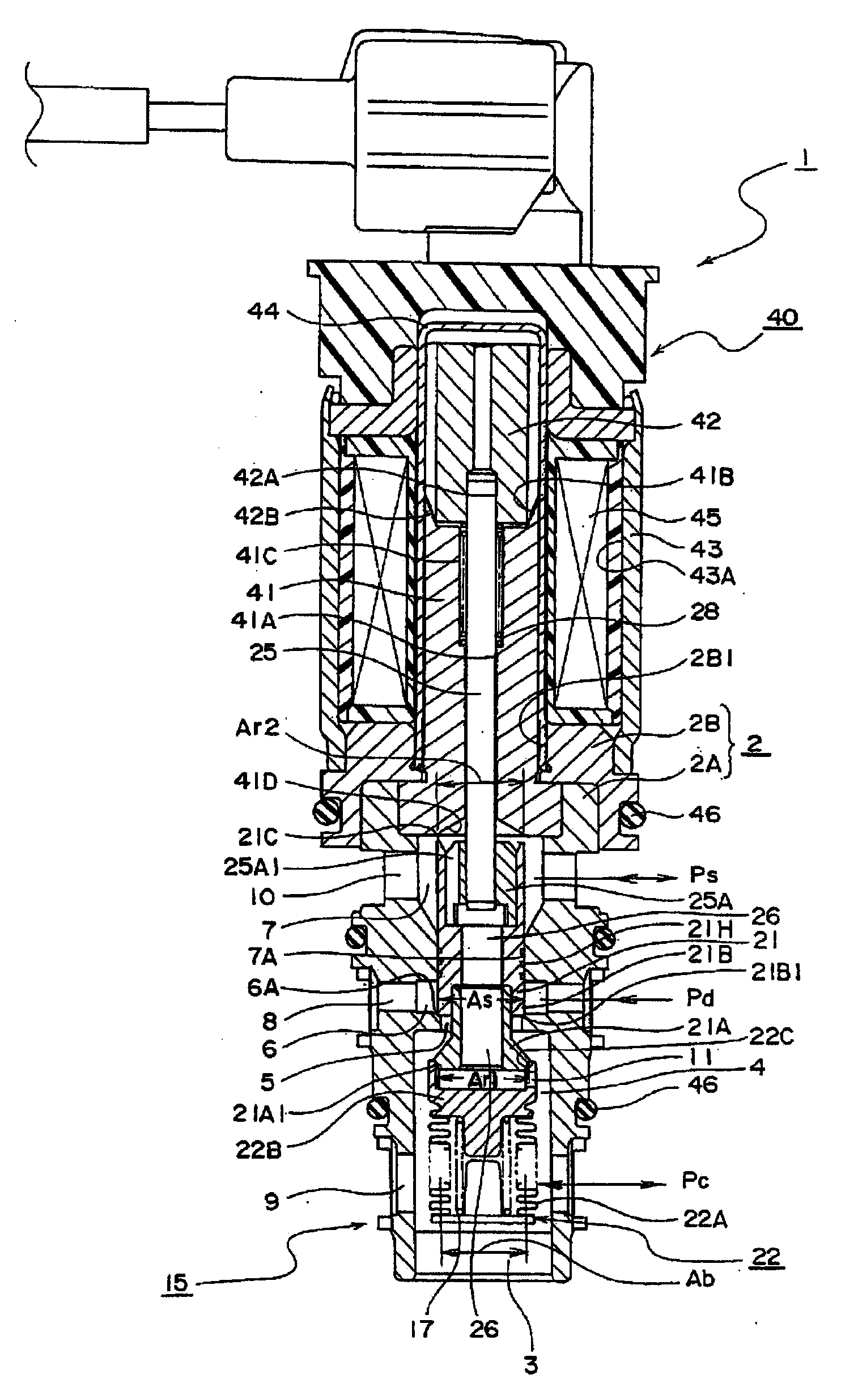
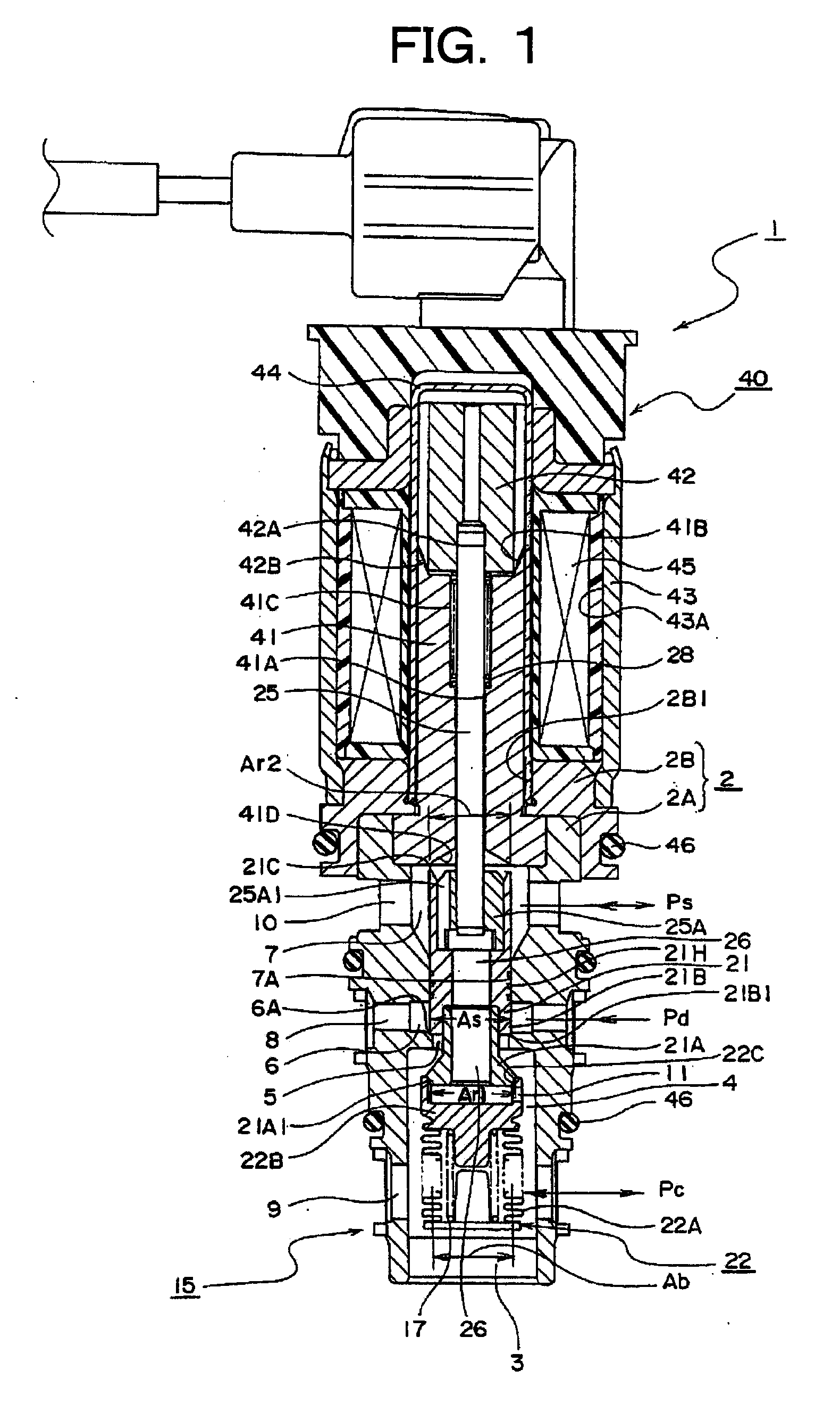
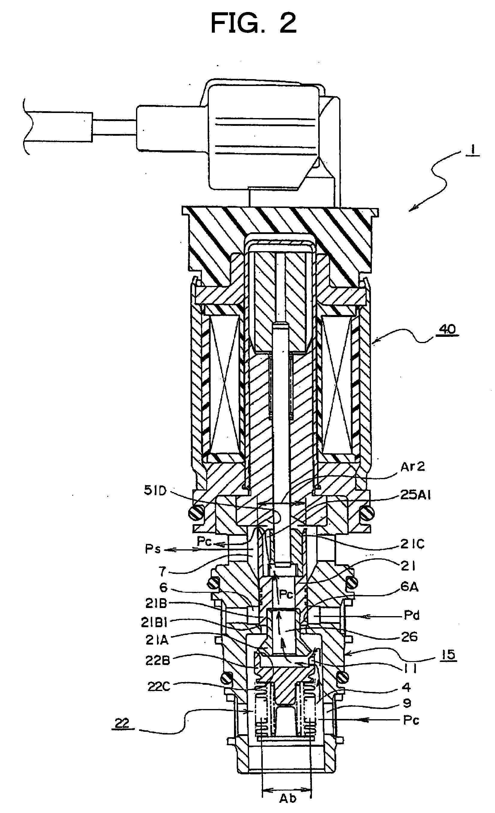
[0020]In a displacement control valve according to the present invention, when the ambient temperature drops during night its refrigerant liquid remains within the control chamber which is located inside the refrigerant compressor. The displacement control valve of the present invention, however, has an advantage of being capable of vaporizing refrigerant liquid in the control chamber and starting cooling operation ten to fifteen times faster than conventional displacement control valves do, because the control chamber is designed to be communicatable, via auxiliary communication passage and intermediate communication passage, with the third communication passage under influence of suction pressure. This quick start-up of cooling operation is made possible with no need of design alternation to the control chamber related to the displacement control valve or air conditioner. The displacement control valve therefore not only is outstanding in cooling control performance but also has an advantage of reducing manufacture cost for air conditioner as well as displacement control valve.
[0021]Further, a minimum displacement in compressor can be achieved during cooling operation of the air conditioner. Closing action of the third valve member prevents the fluid in control chamber under the influence of control pressure from reaching the third communication passage. Opening action of the second valve member then permits a transition to discharge pressure state, which enables the displacement control valve to maintain the pressure in the control chamber above a preset value and stop the compressor from cooling the passenger compartment. It also has an advantage of minimizing the operation cost of the air conditioner.

Problems solved by technology

However, normal pressure control in the crank chamber 155 becomes problematic and this cross-sectional area cannot be enlarged.
Thus, without increasing the refrigerant flow rate out of the crank chamber 155, the compressor does not operate at a normal capacity for an extended time up to 5 minutes and passenger comfort is poor for several minutes more.

Method used


Image

  • Displacement Control Valve
  • Displacement Control Valve
  • Displacement Control Valve

Examples


first embodiment

[0128]FIG. 4 is a partial cross-sectional view of the displacement control valve 1 showing the In the displacement control valve 1 of FIG. 4, a different point from the displacement control valve 1 of FIG. 1 is that the auxiliary communication passage 11 penetrates from a side face of the first valve member 21A to the intermediate communication passage 26. The auxiliary communication passage 11 may be provided on the valve seating portion 22B, further, it may be provided on the first valve member 21A. Also, it may be provided on both the valve seat portion 22B and the first valve member 21A. Namely, if the auxiliary communication passage 11 has a constitutions that enables communication from the first valve chamber 4 to the intermediate communication passage 26, then it may be provided at anywhere. Also, a third communication passage 10 side of the intermediate communication passage 26 may be a communication passage formed by the shape of the solenoid rod 25 (this communication pas...

second embodiment

[0129]FIG. 5 is a partial cross-sectional view of the displacement control valve of a In the displacement control valve 1 of the FIG. 5, a constitution different from the displacement control valve 1 of FIG. 1 is that the auxiliary communication passages 11 are provided on both of the first valve member 21A and the valve seat portion 22B. It is better that a diameter A of the auxiliary communication passage 11 is a half of the case of FIG. 1 of respective flow amount cross section area. Other constructions are the same as FIG. 1. Note that, the effective pressure receiving area Ab of the pressure sensing device 22, the pressure receiving area Ar1 of the first valve member 21A and sealing pressure receiving area As of the second valve member 21B are about identical. Note that, FIG. 5 shows a status that the first valve seat portion 22B and the first valve portion 21A are slightly open by acting the suction pressure Ps (refer to FIG. 1) to the valve seat portion 22B. From the valve o...


PUM


Abstract

The present invention comprising a valve main body having a first valve chamber, a second valve chamber and a third valve chamber, said first valve chamber communicating with a first communication passage, said second valve chamber having a second valve seat face for a valve hole and communicating with a second communication passage, said third valve chamber having a third valve seat face and communicating with a third communication passage; a valve body having a first valve member, a second valve member and a third valve member, said second valve member having a intermediate communication passage therein communicating with said first valve chamber and said third communication passage, said second valve member opening and closing a valve hole with respect to second valve seat face, thereby communicating with said first valve chamber and said second valve chamber, said third valve member performing a valve opening / closing action with respect to said third valve seat face in an reverse manner against said second valve member, thereby opening or closing the communication with said intermediate communication passage and said third communication passage, said first valve member performing a valve opening / closing action in the same direction to said second valve member; a pressure sensing member having a valve seat portion, said valve seat portion being disposed at a free end of said pressure sensing member, said valve seat portion performing a valve opening / closing action with respect to said first valve member, thereby opening or closing the communication with said first valve chamber and said intermediate communication passage; and a solenoid member driving said valve body in accordance with an electric current supplied thereto; and an auxiliary communication passage providing a communication between said first valve chamber and said intermediate communication passage.

Description

TECHNICAL FIELD[0001]This invention relates to a displacement control valve for modulating an air conditioner. More particularly, the invention relates to a displacement control valve with which the control chamber is able to modulate a compressor in an air conditioner regardless of outside temperature.BACKGROUND ART[0002]As a related art of the present invention, there is a constitution that a displacement control valve is attached to a variable displacement compressor (for example, refer to Patent Document 1 described in a following column 0011). A constitution which is similar with the variable displacement compressor is shown in FIG. 6. FIG. 6 is whole cross sectional views showing a displacement control valve connected with a variable displacement compressor. A displacement control valve 100 is equipped within a mounting portion which is not shown in the displacement control type compressor 100. However, in order to clarify the displacement control valve 100, the valve is shown...

Claims


Application Information

Patent Timeline
Patent Type & Authority Applications(United States)
IPC IPC(8): F16K31/06F16K31/124
CPCF04B27/1804F04B2027/1845F04B2027/1831F04B2027/1827Y10T137/7762Y10T137/7761Y10T137/0329
Inventor IWA, TOSHIAKICHO, RYOSUKEHIRATA, ICHIROWARREN, MATTHEW R.GUTIERREZ, ERNEST JOSE
Owner MAHLE INT GMBH
Learn More