
Crop lifter pans

a technology of lifting pans and crop, applied in the field of crop lifting pans, can solve the problems of inability to cut crop heads with a conventional harvest header, inherently short, and easy to fall down

Inactive Publication Date: 2009-07-23
DIETRICH GMBH
View PDF39 Cites 6 Cited by
  • Summary
  • Abstract
  • Description
  • Claims
  • Application Information

AI Technical Summary

Benefits of technology

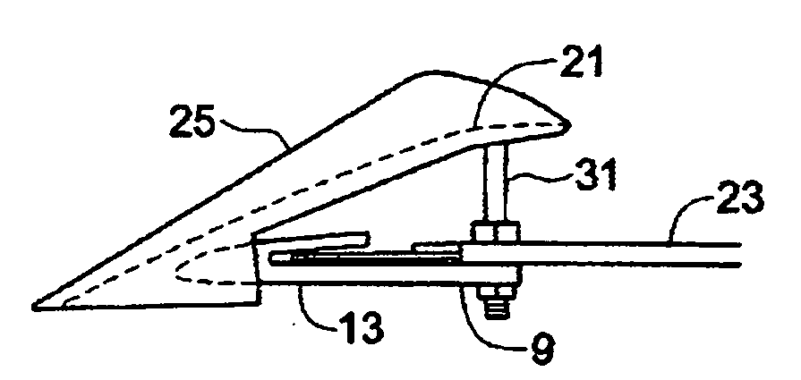
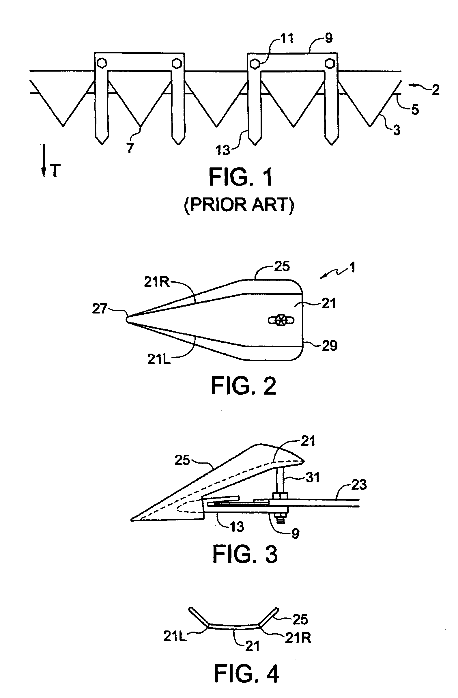
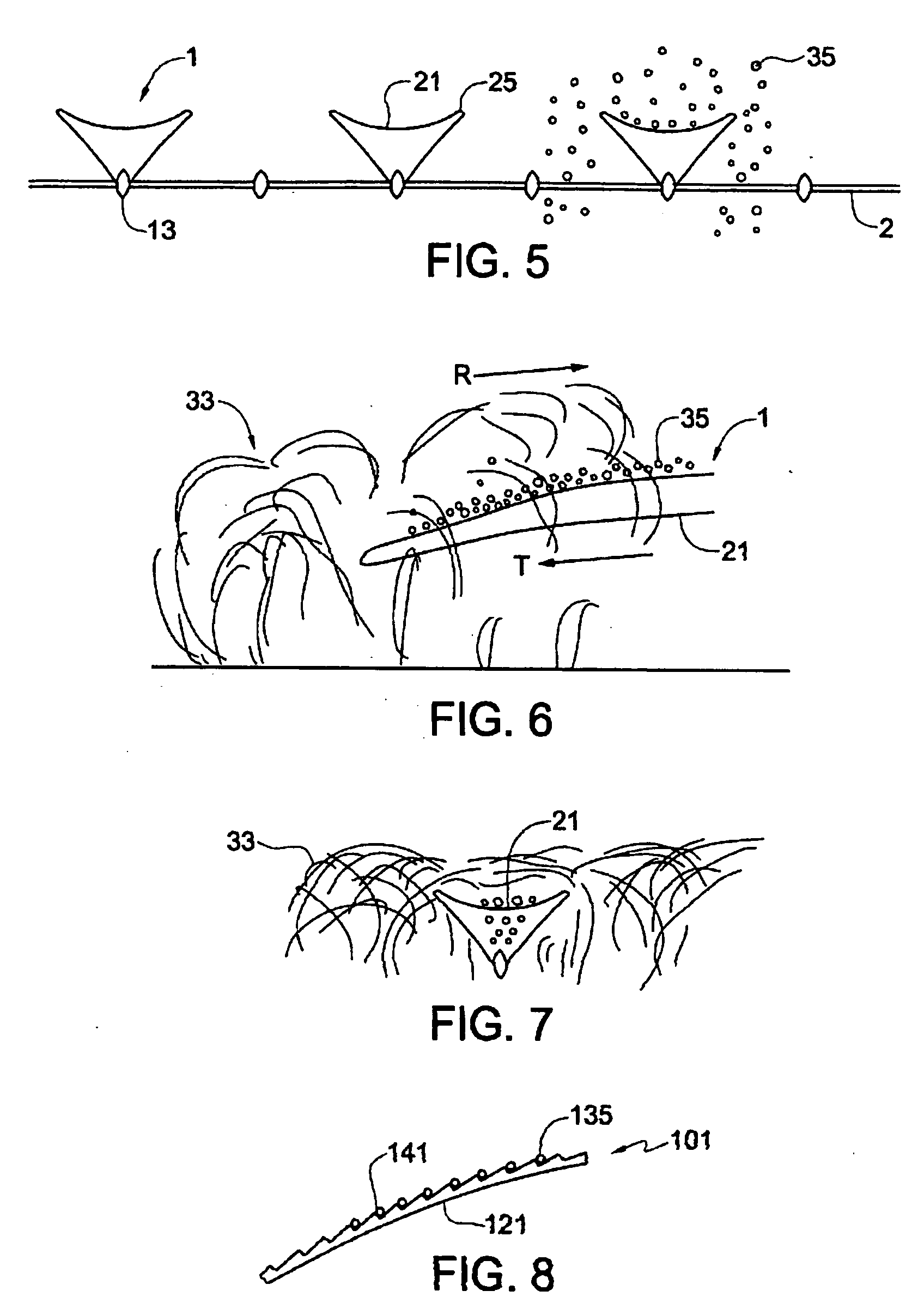
"The present invention provides a seed pan apparatus for a cutting header that overcomes problems in the prior art. The apparatus includes a seed pan that is attached to the cutting header and extends upward and rearward from a guard finger of a knife guard over the knife to a rear end located rearward of the knife. The seed pan has side walls that extend upward from side edges of the seed pan, and right and left side edges of the seed pan diverge from a front end thereof to the rear end thereof such that the rear end of the seed pan is wider than the front end thereof. The apparatus catches a significant proportion of seeds that fall from shattered pod and heads, and helps to raise pods attached to the stalks to a level where same can be cut. This improves the efficiency of the cutting process and increases the chances of the pod passing onto the header."

Problems solved by technology

For various reasons crops sometimes are lying so close to the ground that it is difficult to cut them with a conventional harvest header.
Some crops are inherently short, while others may be taller, but are prone to fall down when they reach maturity.
A conventional knife is a few inches above the ground when the header is in its lowest position, such that very short or downed crop material will pass under the knife and be lost.
Much loss often occurs in straight cut harvesting of crops such as dry beans, peas, and lentils due to pods shattering or pods that are below the cutter bar.
The narrow fingers however allow pods to hang down on each side of the rod as the stalk moves rearward along the finger, such that some pods are below the knife when the stalk is cut, and therefore drop to the ground and are lost.
As well, seed pods often shatter when contacted by the harvesting equipment before they are on the header, and the shattered pods spill their seeds to fall on the ground.
While this problem of shattering seed pods and heads is more severe in some crops than others, there is generally at least some shattering loss in any crop.

Method used


Image

  • Crop lifter pans
  • Crop lifter pans
  • Crop lifter pans

Examples


Embodiment Construction

[0024]A typical cutting header comprises a knife extending along the front lower edge of the header, which is moved along a field in an operating travel direction T. The knife 2 comprises, as schematically illustrated in the bottom view of FIG. 1, a plurality of triangular knife sections 3 attached to a knife bar 5 such that the apex 7 of the triangle extends forward from the bar 5. Guards 9 are attached to the front lower edge of the header with guard bolts 11 and serve to protect the knife sections 3 from breakage when contacting stones and like obstructions. The guards 9 comprise pointed guard fingers 13 extending forward.

[0025]FIGS. 2 and 3 illustrate a seed pan apparatus 1 for attachment to a typical cutting header such as illustrated in FIG. 1. The seed pan apparatus 1 comprises a seed pan 21 adapted at a front portion thereof for attachment to the cutting header 23 such that when attached to the cutting header 23, the seed pan 21 extends upward and rearward from a guard finge...


PUM


Abstract

A seed pan apparatus for attachment to a cutting header hang a knife and cooperating knife guards mounted along a lower front edge thereof includes a seed pan adapted at a front portion thereof for attachment to the cutting header such that when attached to the cutting header, the seed pan extends upward and rearward from a guard finger of a knife guard over the knife to a rear end thereof located rearward of the knife. Side walls extend upward from side edges of the seed pan, and right and left side edges of the seed pan diverge from a front end thereof to the rear end thereof such that the rear end of the seed pan is wider than the front end thereof.

Description

[0001]This invention is in the field of agricultural harvesting equipment and in particular equipment for cutting crops.BACKGROUND[0002]For various reasons crops sometimes are lying so close to the ground that it is difficult to cut them with a conventional harvest header. Some crops are inherently short, while others may be taller, but are prone to fall down when they reach maturity.[0003]Typically the knife on cutting headers comprises a knife bar extending along the front lower edge of the header, with a plurality of triangular knife sections attached to the bar such that the apex of the triangle extends forward from the bar. The exposed side edges of the knife sections are sharpened. Guards are attached to the front lower edge of the header and serve to protect the knife sections from breakage when contacting stones and like obstructions. The guards comprise pointed guard fingers extending forward, and the knife moves back and forth along the edge of the header in a slot cut lat...

Claims


Application Information

Patent Timeline
Patent Type & Authority Applications(United States)
IPC IPC(8): A01D43/00
CPCA01D41/12A01D45/22A01D41/14
Inventor HERMAN, ARDONDIETRICH
Owner DIETRICH GMBH
Learn More