
Processor including efficient signature generation for logic error protection

a logic error and processor technology, applied in the field of processors, can solve problems such as data errors, components that include memory arrays may have bit failures, and electronic components may fail in a variety of ways

Active Publication Date: 2009-07-16
ADVANCED MICRO DEVICES INC
View PDF21 Cites 22 Cited by
  • Summary
  • Abstract
  • Description
  • Claims
  • Application Information

AI Technical Summary

Benefits of technology

[0007]Various embodiments of a processor including efficient signature generation for logic error protection are disclosed. In one embodiment, a processor core may operate in a normal execution mode and a reliable execution mode. The processor core includes an instruction decode unit that may be configured to dispatch a same integer instruction stream to a plurality of integer execution units when operating, for example, in the reliable execution mode. The plurality of integer execution units may be configured to operate in lock-step such that during each clock cycle, the plurality of integer execution units executes the same integer instruction, and should therefore have identical results. The processor core also includes signature generation logic that may generate a respective signature from result signals conveyed on respective result buses in one or more pipeline stages within each respective one of the plurality of integer execution units in response to the result signals becoming available. The signature generation unit may generate the signatures concurrently with execution of the integer instructions. The processor core also includes compare logic that is coupled to the signature generation logic and may be configured to detect a mismatch between signatures from each of the plurality of integer execution units. Further, in response to the compare logic detecting any mismatch, the compare logic may be configured to cause instructions causing the mismatch to be re-executed.

Problems solved by technology

Electronic components may fail in a variety of ways.
Components that include memory arrays may have bit failures that may manifest as data errors.
Logic circuits may have stuck-at bits and / or delay errors.
Many errors may be caused by manufacturing defects.
For example, during manufacturing, particulate contamination can cause hard errors to appear both immediately and during later operation.
Many of these errors may be classified as hard errors since once a failure is detected the failure is persistent.
Although many hard errors may be detected during manufacturing test and burn-in, some may be more latent, or are just not caught.
Some types of errors may be more damaging than others.
For example, silent errors such as those that occur from corrupt memory data can be catastrophic, as there may be no way to recover unless the error is detected and either corrected or a recovery mechanism exists.
Since most logic errors in the past were caught during manufacturing test and burn-in, the logic has been left largely unprotected.
Soft errors, on the other hand, may be intermittent and appear random, and as such can be difficult to detect and correct.
In the past, soft errors were typically isolated to systems that used cables and boards with connectors and the like.
Now however, as manufacturing technologies advance and device sizes get smaller (e.g., <90 nm), another source of soft errors is emerging particularly in metal oxide semiconductor (MOS) devices.
These new soft errors may be caused by neutron or alpha particle bombardment and may manifest as memory errors due to direct memory array bombardment, or logic errors as a result of logic element (e.g., flip-flop) bombardment.
In devices such as microprocessors, which contain millions of transistors, soft errors, if not detected, may cause catastrophic results.
In many conventional chip level redundancy schemes, the detection of such errors cannot be corrected and the system cannot recover transparently since the errors have already corrupted the processor internal execution states, thus requiring a reboot.
Thus, although the error may be caught, this type of arrangement may not be acceptable in high reliability and high availability systems.

Method used


Image

  • Processor including efficient signature generation for logic error protection
  • Processor including efficient signature generation for logic error protection
  • Processor including efficient signature generation for logic error protection

Examples


Embodiment Construction

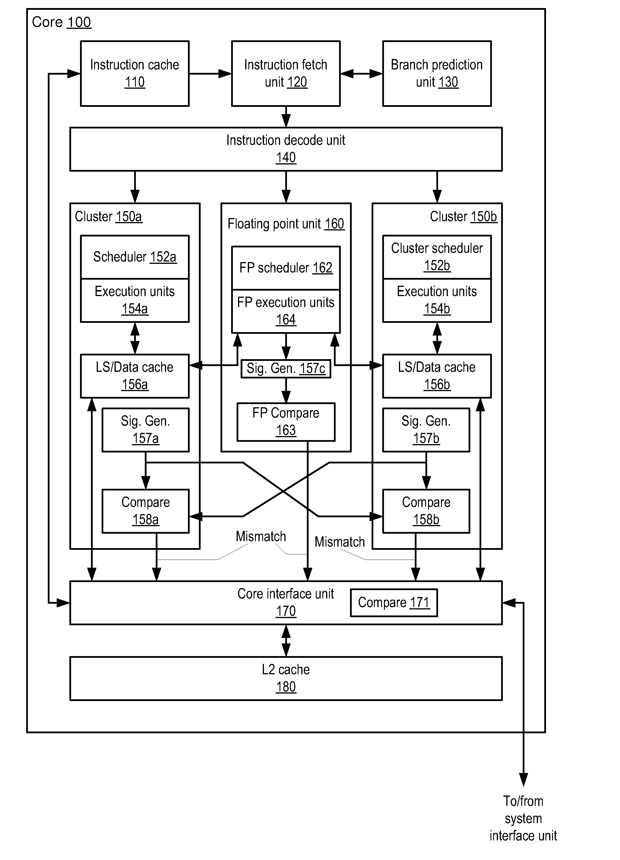
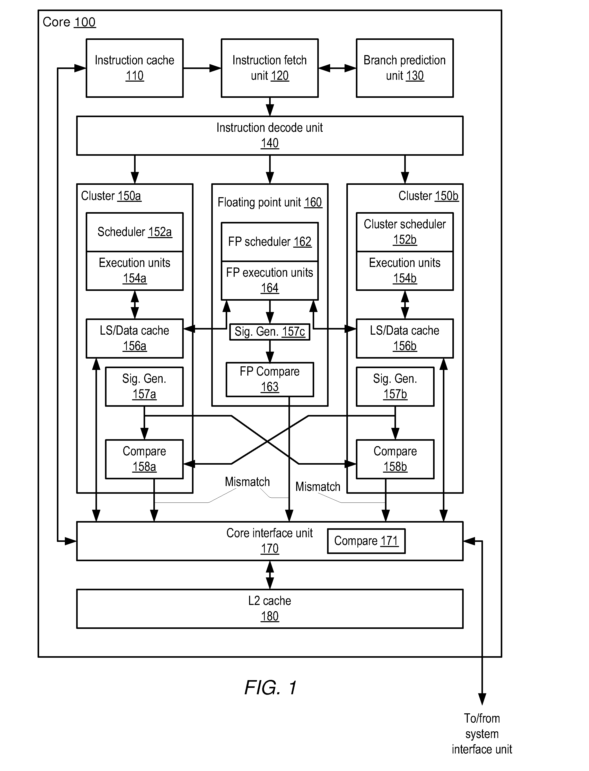
[0014]One embodiment of a processor core 100 is illustrated in FIG. 1. Generally speaking, core 100 may be configured to execute instructions that may be stored in a system memory (shown in FIG. 5) that is directly or indirectly coupled to core 100. Such instructions may be defined according to a particular instruction set architecture (ISA). For example, core 100 may be configured to implement a version of the x86 ISA, although in other embodiments core 100 may implement a different ISA or a combination of ISAs.

[0015]In the illustrated embodiment, core 100 may include an instruction cache (IC) 110 coupled to provide instructions to an instruction fetch unit (IFU) 120. IFU 120 may be coupled to a branch prediction unit (BPU) 130 and to an instruction decode unit 140. Decode unit 140 may be coupled to provide operations to a plurality of integer execution clusters 150a-b as well as to a floating point unit (FPU) 160. Each of clusters 150a-b may include a respective cluster scheduler ...


PUM


Abstract

A processor core includes an instruction decode unit that may dispatch a same integer instruction stream to a plurality of integer execution units operating in lock-step. The processor core also includes signature generation logic that may generate, concurrently with execution of the integer instructions, a respective signature from result signals conveyed on respective result buses in one or more pipeline stages within each of the integer execution units in response to the result signals becoming available. The processor core also includes compare logic that may detect a mismatch between signatures from each of the integer execution units. Further, in response to the compare logic detecting any mismatch, the compare logic may cause instructions causing the mismatch to be re-executed.

Description

BACKGROUND OF THE INVENTION[0001]1. Field of the Invention[0002]This invention relates to processors and, more particularly, to logic error protection within the processor.[0003]2. Description of the Related Art[0004]Electronic components may fail in a variety of ways. Components that include memory arrays may have bit failures that may manifest as data errors. Logic circuits may have stuck-at bits and / or delay errors. The list goes on. Many errors may be caused by manufacturing defects. For example, during manufacturing, particulate contamination can cause hard errors to appear both immediately and during later operation. Many of these errors may be classified as hard errors since once a failure is detected the failure is persistent. Although many hard errors may be detected during manufacturing test and burn-in, some may be more latent, or are just not caught. Some types of errors may be more damaging than others. For example, silent errors such as those that occur from corrupt me...

Claims


Application Information

Patent Timeline
Patent Type & Authority Applications(United States)
IPC IPC(8): G06F9/302
CPCG06F9/30189G06F9/3851G06F9/3891G06F9/3861G06F9/3885G06F9/3857G06F9/3858G06F9/3854
Inventor QUACH, NHON
Owner ADVANCED MICRO DEVICES INC
Learn More