
Processing Unit Incorporating L1 Cache Bypass

a processing unit and cache bypass technology, applied in computing, memory adressing/allocation/relocation, instruments, etc., can solve the problem of reducing the likelihood of the requested data casting out frequently used data from the higher level cache by bypassing storage in the higher level cach

Inactive Publication Date: 2009-07-16
IBM CORP
View PDF6 Cites 61 Cited by
  • Summary
  • Abstract
  • Description
  • Claims
  • Application Information

AI Technical Summary

Benefits of technology

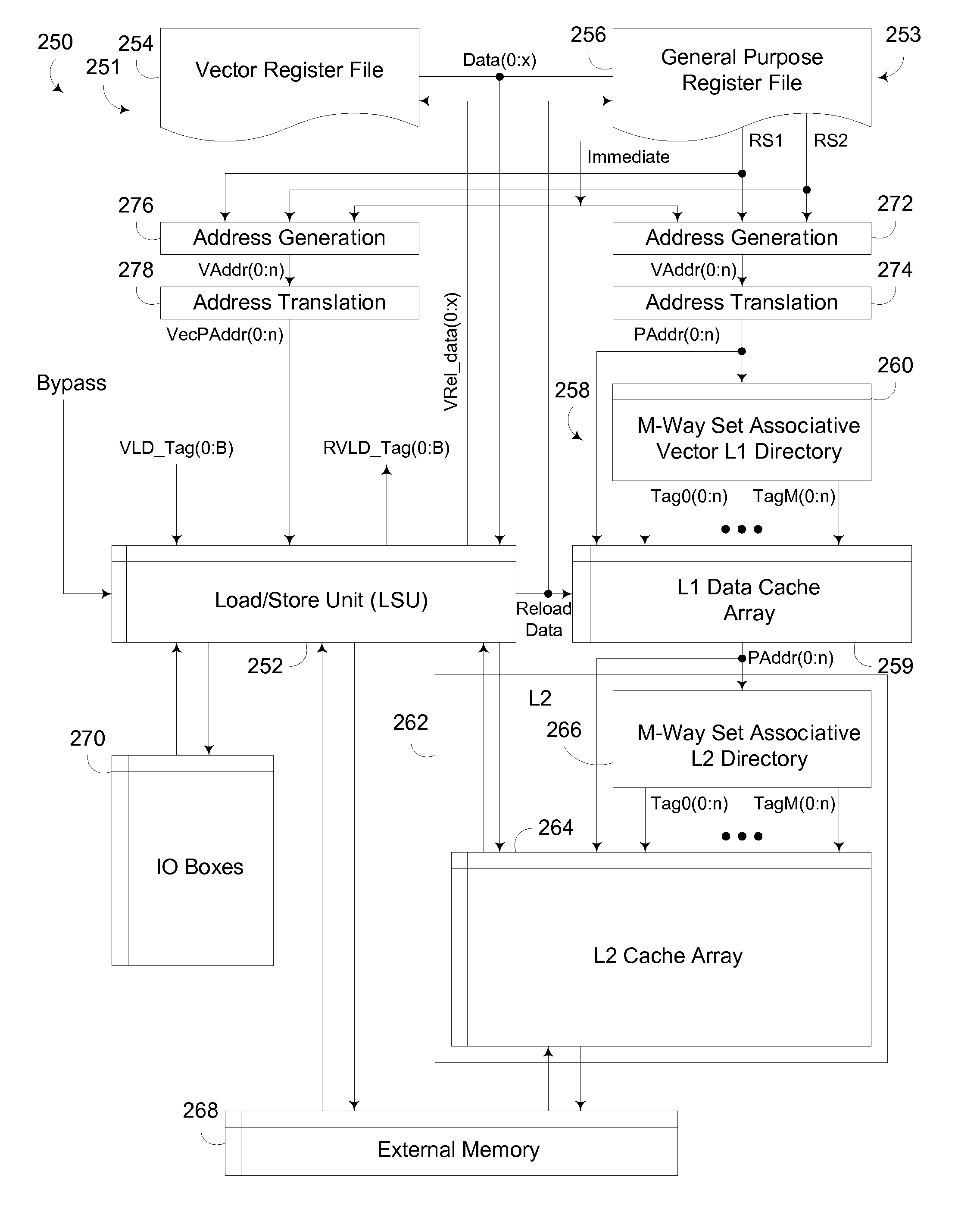
[0011]The invention addresses these and other problems associated with the prior art by providing a circuit arrangement and method that bypass the storage of requested data in a higher level cache of a multi-level memory architecture during the return of the requested data to a requester, while caching the requested data in a lower level cache. Thus, for certain types of data, e.g., vertex data used in image processing, or other data that is only used once and / or that is rarely modified or written back to memory, bypassing storage in a higher level cache reduces the likelihood of the requested data casting out frequently used data from the higher level cache. In addition, by caching the data in a lower level cache, the lower level cache can still snoop data requests and return requested data in the event the data is already cached in the lower level cache.
[0012]Consistent with one aspect of the invention, a requester is configured to generate a request for data from a multi-level memory architecture. First and second caches are disposed in the multi-level memory architecture, with the first cache disposed at a higher level in the multi-level memory architecture than the second cache. Control logic coupled to the first and second caches is configured to, in response to the request, retrieve the requested data from the multi-level memory architecture, cause the requested data to be cached in the second cache, forward the requested data to the requester, and bypass caching of the requested data in the first cache.

Problems solved by technology

Thus, for certain types of data, e.g., vertex data used in image processing, or other data that is only used once and / or that is rarely modified or written back to memory, bypassing storage in a higher level cache reduces the likelihood of the requested data casting out frequently used data from the higher level cache.

Method used


Image

  • Processing Unit Incorporating L1 Cache Bypass
  • Processing Unit Incorporating L1 Cache Bypass
  • Processing Unit Incorporating L1 Cache Bypass

Examples


Embodiment Construction

[0023]Embodiments consistent with the invention implement an L1 cache bypass technique to bypass the storage of requested data in a higher level cache of a multi-level memory architecture during the return of the requested data to a requester, while caching the requested data in a lower level cache. Thus, for certain types of data, e.g., vertex data used in image processing, or other data that is only used once and / or that is rarely modified or written back to memory, bypassing storage in a higher level cache reduces the likelihood of the requested data casting out frequently used data from the higher level cache, e.g., program stacks and / or local variables. In addition, by caching the data in a lower level cache, the lower level cache can still snoop data requests and return requested data in the event the data is already cached in the lower level cache.

Hardware and Software Environment

[0024]Now turning to the drawings, wherein like numbers denote like parts throughout the several ...


PUM


Abstract

A circuit arrangement and method bypass the storage of requested data in a higher level cache of a multi-level memory architecture during the return of the requested data to a requester, while caching the requested data in a lower level cache. For certain types of data, e.g., data that is only used once and / or that is rarely modified or written back to memory, bypassing storage in a higher level cache reduces the likelihood of the requested data casting out frequently used data from the higher level cache. By caching the data in a lower level cache, however, the lower level cache can still snoop data requests and return requested data in the event the data is already cached in the lower level cache.

Description

FIELD OF THE INVENTION[0001]The invention is generally related to data processing, and in particular to processor architectures and execution units incorporated therein.BACKGROUND OF THE INVENTION[0002]As semiconductor technology continues to inch closer to practical limitations in terms of increases in clock speed, architects are increasingly focusing on parallelism in processor architectures to obtain performance improvements. At the chip level, multiple processor cores are often disposed on the same chip, functioning in much the same manner as separate processor chips, or to some extent, as completely separate computers. In addition, even within cores, parallelism is employed through the use of multiple execution units that are specialized to handle certain types of operations. Pipelining is also employed in many instances so that certain operations that may take multiple clock cycles to perform are broken up into stages, enabling other operations to be started prior to completio...

Claims


Application Information

Patent Timeline
IPC IPC(8): G06F12/08
CPCG06F12/0888G06F12/0811
Inventor COMPARAN, MIGUELMEJDRICH, ERIC OLIVERMUFF, ADAM JAMES
Owner IBM CORP
Learn More