
Multi-objective optimal design support device and method taking manufacturing variations into consideration

Inactive Publication Date: 2009-07-16
FUJITSU LTD
View PDF15 Cites 19 Cited by
  • Summary
  • Abstract
  • Description
  • Claims
  • Application Information

AI Technical Summary

Benefits of technology

[0021]It is an object of the present invention to realize visualization based on objective functions (display of a Pareto boundary, etc.) in a short time and to be able to catch a relation between an objective function and a design parameter or another objective function taking manufacturing errors into consideration while properly displaying an Pareto optimal solution on the basis of it.
[0035]According to the devices or method disclosed by this specification, in the feasible region display in the objective space, sensitivity information for indicating the sensitivity of a design parameter at the point can be displayed in relation to each point in the feasible region, in particular a Pareto frontier point. Therefore, a design specification having strong robustness against a manufacturing variation (manufacturing error) which can satisfies a Pareto optimal solution in a feasible region and also an objective function can be easily caught.
[0036]Furthermore, according to the devices or method disclosed by this specification, an objective function can be approximated according to a mathematical expression, such as a polynomial and the like using some sample sets of design parameters of the slider shape of a hard disk and the like and the expression can be computed by a mathematical processing method. Thus, since input parameters can be handled without performing any process, a logical relation and an input / output relation between objective functions can be easily caught.

Problems solved by technology

However, since the points 2402-1 and 2402-4 can be made lighter and more inexpensive, they cannot be optimal solutions.
However, even if an optimal parameter can be determined with much labor in such a situation, the occurrence of an error in an actual manufacturing process, such as material cutting and the like cannot be avoided.
Furthermore, if an error is independently considered for each parameter, a required performance can be hardly achieved.
A design support method capable of display the required performance even when there are somewhat errors in such a situation has not been established yet.
Therefore, optimization takes very much time.
However, in the above prior art, since it is necessary to do an optimization computation accompanying expensive flying height computation over again from the beginning, the number of sets of weight vectors to attempt when designing is limited.
Furthermore, since the minimization of a function value f can be applied to only one point on the Pareto curved surface, it is difficult to predict an optimal relation between objective functions.
Therefore, information about such an optimal relation cannot also be fed back.
As described above, conventionally, since a multi-objective optimization process itself takes very much time, it is difficult even to display a correct Pareto optimal solution, much less exits a Pareto optimal solution determination support method taking manufacturing errors into consideration.

Method used


Image

  • Multi-objective optimal design support device and method taking manufacturing variations into consideration
  • Multi-objective optimal design support device and method taking manufacturing variations into consideration
  • Multi-objective optimal design support device and method taking manufacturing variations into consideration

Examples


Embodiment Construction

[0063]The preferred embodiments of the present invention are described in detail below with reference to the drawings.

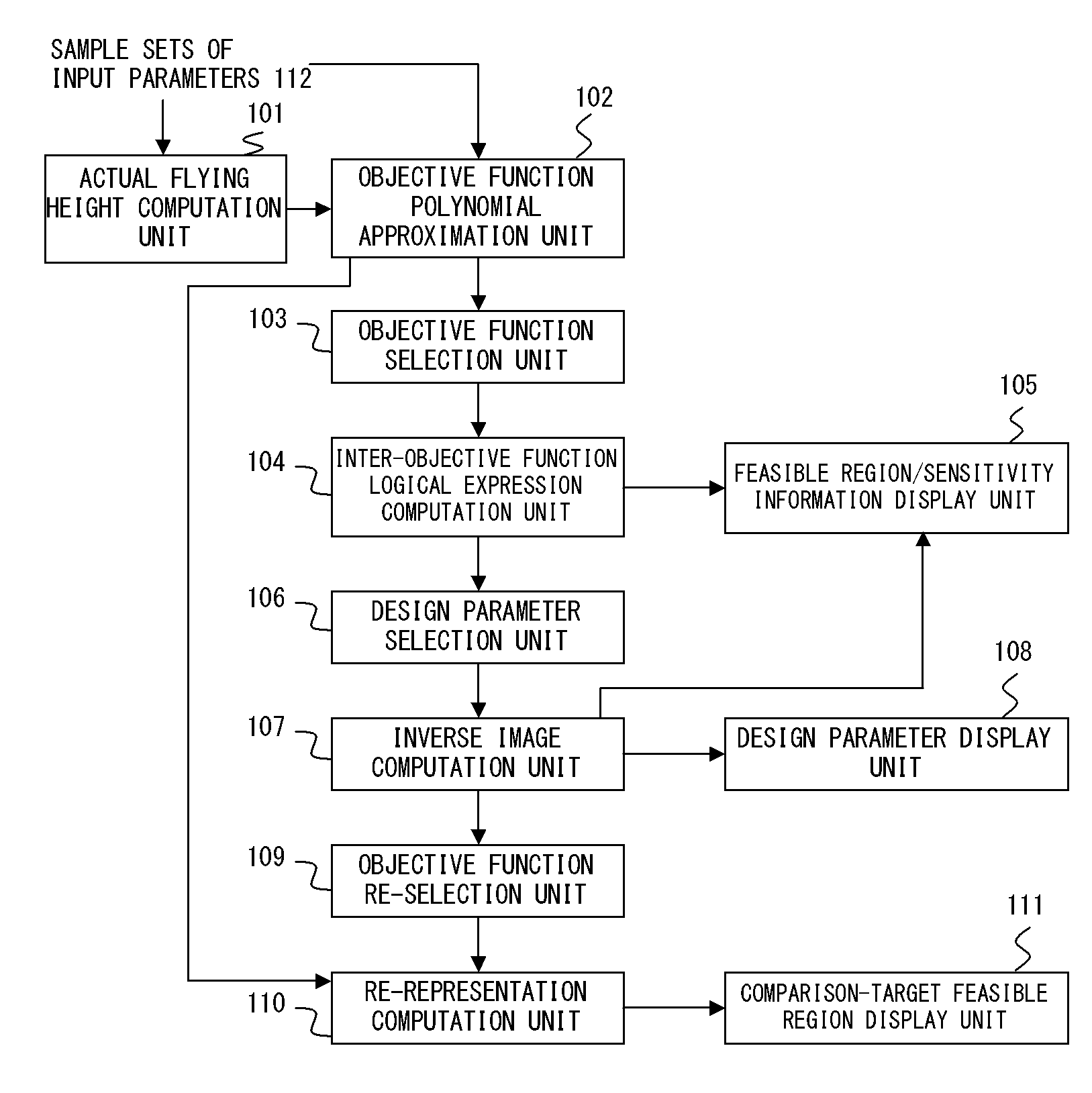
[0064]FIG. 4 shows the functional block configuration of the preferred embodiment of the present invention.

[0065]The actual flying height computation unit 101 is a sample-set objective function computation unit for obtaining the input of sample sets of the input parameters 112 of the slider shape of a hard disk, applying a slider flying height computation to each set and outputting each objective function value. In this case, the number of the sample sets of input parameters 112 is at most approximately several hundreds.

[0066]The objective function polynomial approximation unit 102 is an objective function approximation unit for approximating each objective function of a slider shape by the polynomial of a multiple regression equation and the like based on a multiple regression analysis, using sample sets of input parameters 112 and each objective function value of e...


PUM


Abstract

A logical expression indicating a logical relation between arbitrary two or three objective functions, of a plurality of mathematically approximated objective functions is computed. A feasible region / sensitivity information display unit displays the feasible region in arbitrary objective space according to it. An inverse image computation unit computes a point or area in design space corresponding to arbitrary design parameters in relation to a point or area specified by a user in the feasible region of the objective space. A feasible region / sensitivity information display unit displays the distribution state of the corresponding point or area as sensitivity information in relation to the specified point or area in the feasible region.

Description

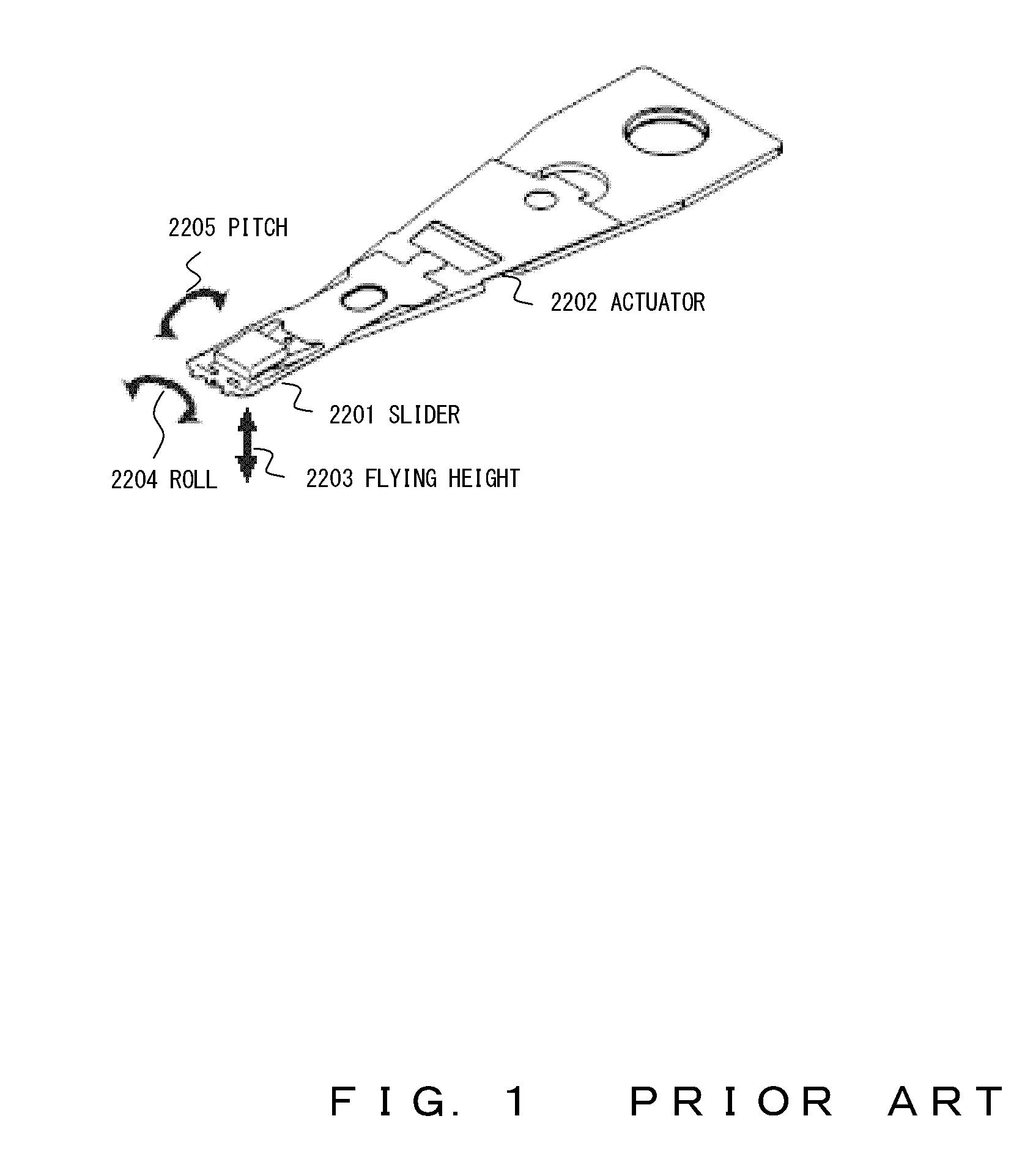
CROSS REFERENCE TO RELATED APPLICATIONS [0001]This application is based upon and claims the benefit of priority of the prior Japanese Patent Application No. 2008-005106, filed on Jan. 14, 2008, the entire contents of which are incorporated herein by reference.BACKGROUND OF THE INVENTION [0002]1. Field of the Invention[0003]The present invention relates to a multi-objective optimal design support technique suitable for the design of the slider shape of a hard disk and the like.[0004]2. Description of the Related Art[0005]Along with the promotion of a high-density / high-capacity hard disk, a distance between a magnetic disk and a head has been increasingly reduced and slider design having the small change in the altitude difference of a disk surface and the amount of fly in a disk radius position is required.[0006]As shown in FIG. 1, a slider 2201 is mounted in the tip lower part of an actuator 2202 moving on the magnetic disk in the hard disk and a header position is computed on the b...

Claims


Application Information

Patent Timeline
IPC IPC(8): G06F15/18
CPCG06F17/50G11B5/10G06F2217/08G06F30/00G06F2111/06G11B21/02
Inventor YANAMI, HITOSHIANAI, HIROKAZUTSUDA, NAOZUMI
Owner FUJITSU LTD
Learn More