Fastener structure with a fine pattern on a surface thereof

a technology of fastener and fine pattern, which is applied in the direction of buckles, other domestic objects, transportation and packaging, etc., can solve the problems of significant variation in the production of external form, color and texture, and achieve the effect of increasing aesthetic appeal

Inactive Publication Date: 2009-07-16
UNIVERSAL TRIM SUPPLY CO LTD
View PDF4 Cites 6 Cited by
  • Summary
  • Abstract
  • Description
  • Claims
  • Application Information

AI Technical Summary

Benefits of technology

[0015](h) Implementing plastic ejection molding: An injection molding machine using the finished mold is employed to manufacture a fastener member, thereby obtaining the fastener member with increased aesthetic appeal.

Problems solved by technology

However, regarding the design aspect of prior art fastener members, there is no area for significant variation in the production of external form, color and texture of decorative designs.

Method used


Image

  • Fastener structure with a fine pattern on a surface thereof
  • Fastener structure with a fine pattern on a surface thereof
  • Fastener structure with a fine pattern on a surface thereof

Examples


Embodiment Construction

[0024]The following descriptions are exemplary embodiments only, and are not intended to limit the scope, applicability or configuration of the invention in any way. Rather, the following description provides a convenient illustration for implementing exemplary embodiments of the invention. Various changes to the described embodiments may be made in the function and arrangement of the elements described without departing from the scope of the invention as set forth in the appended claims.

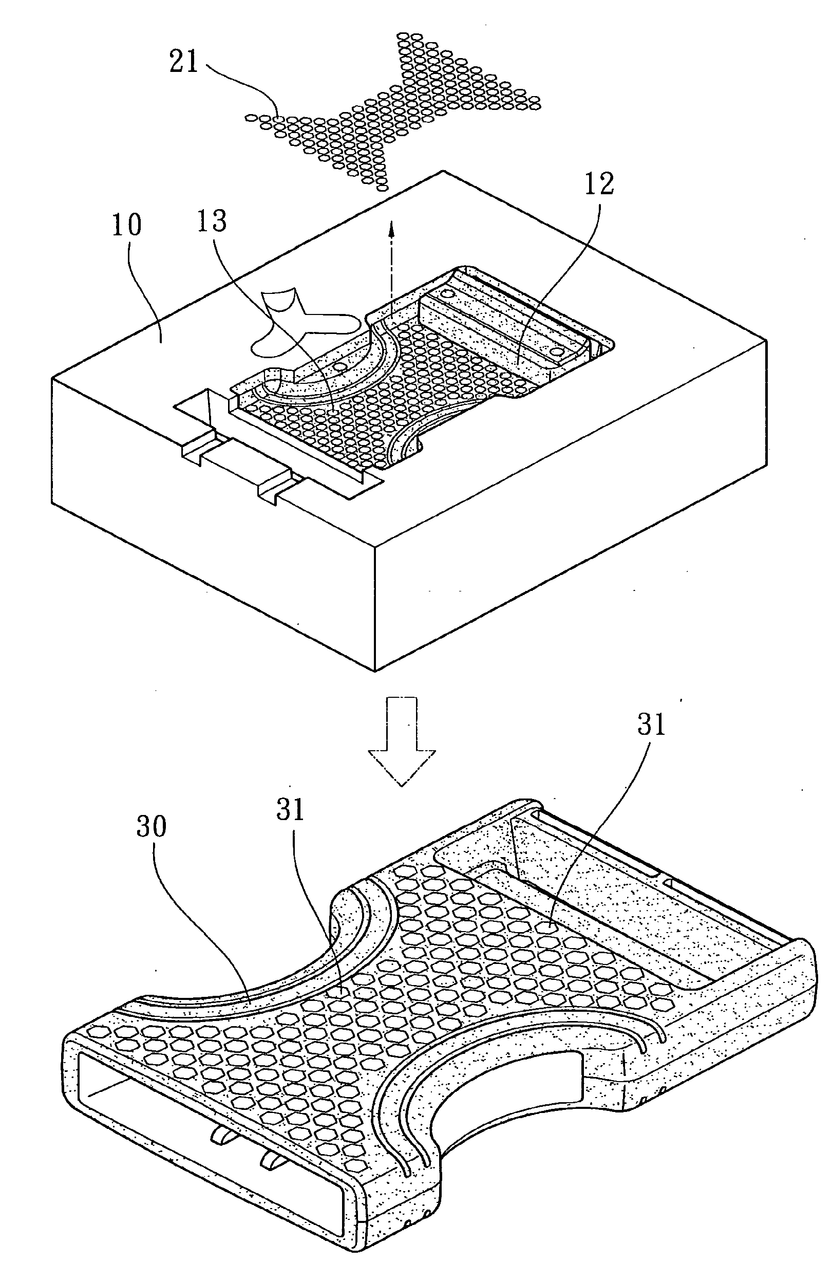
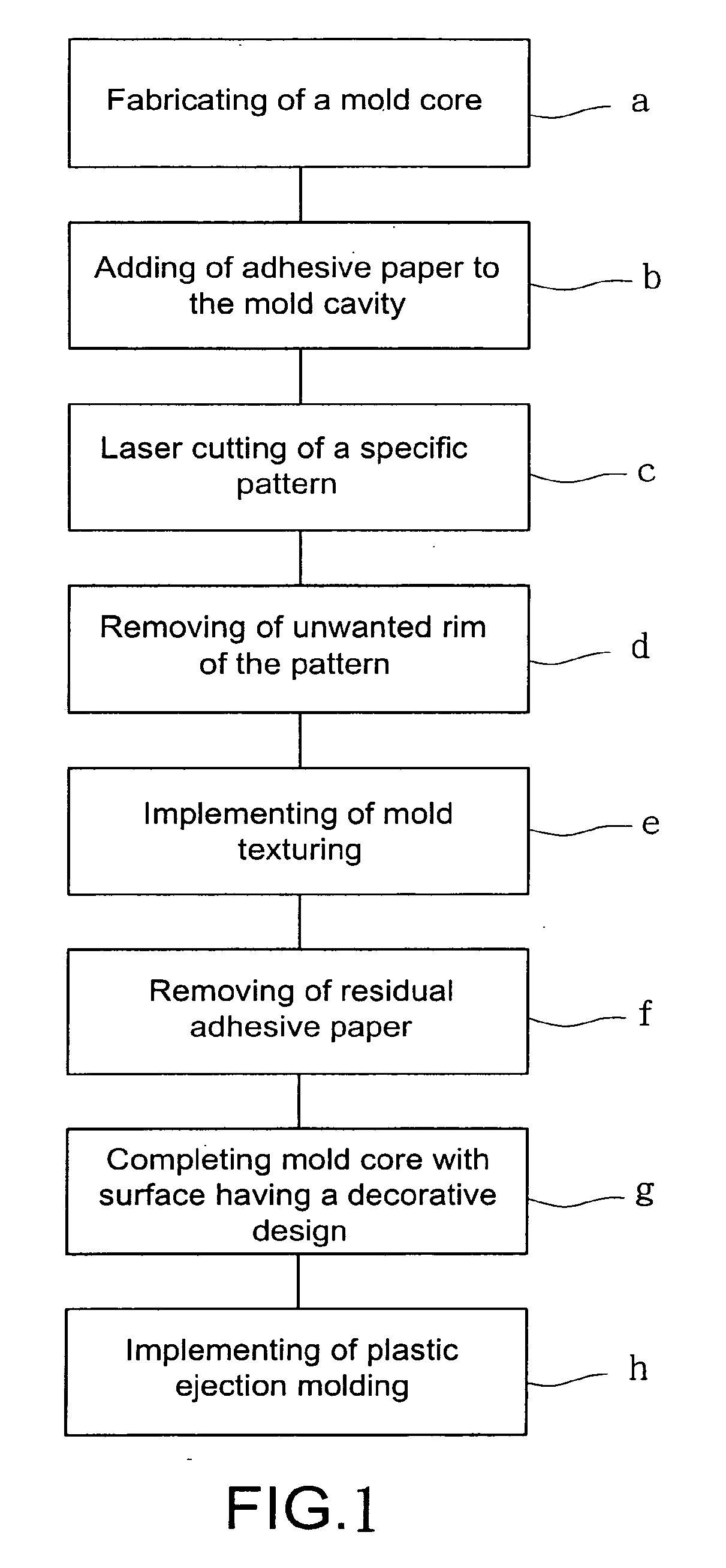
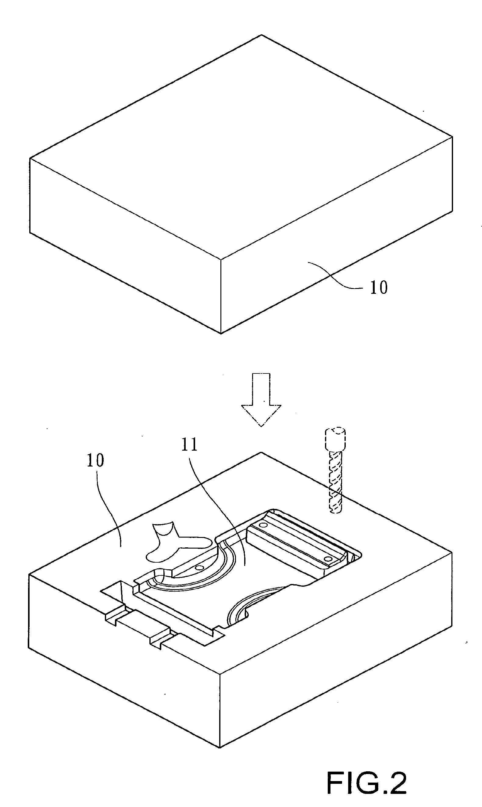
[0025]Referring to FIG. 1, which shows a block flow diagram of a manufacturing method of the fastener member according to the present invention, and in conjunction with FIGS. 2, 3, 4 and 5, particular steps involved to the manufacturing method of the present invention are as described hereinafter:

[0026](a) Fabricating a mold core: A mold core 10 is first manufactured, and a machine tool is used to implement milling to produce a mold cavity 11 having the contour of a fastener member and a smooth surf...


PUM

PropertyMeasurementUnit
depthaaaaaaaaaa
depthaaaaaaaaaa
shapeaaaaaaaaaa

Abstract

A fastener structure with a fine pattern on a surface thereof, wherein a mold core is formed with a mold cavity having a fastener member shape, and a layer of adhesive paper is adhered to an area of the mold cavity desired to be fashioned with a decorative design, then laser engraving machining technology is used to engrave out a specific pattern on the mold cavity. Adhesive paper out of the pattern is removed, and mold texturing (electro-discharge machining) is implemented. Finally, the residual adhesive paper is torn away to reveal a non-textured fine pattern in the mold cavity, and plastic ejection molding is implemented to manufacture a fastener member having a fine pattern, thereby increasing aesthetic appeal of the fastener member.

Description

CROSS-REFERENCE TO RELATED APPLICATION[0001]This is a continuation-in-part of the co-pending patent application Ser. No. 11 / 432,612, filed May 12, 2006.TECHNICAL FIELD OF THE INVENTION[0002]The present invention is related to a fastener structure with a fine pattern on a surface thereof, and in particular to one which is manufactured by incorporating texturing (electro-discharge machining) to the surface of a molded cavity to produce a specific pattern, thereby enabling a surface of an injection molded fastener member to have a decorative design with increased aesthetic appeal.DESCRIPTION OF THE PRIOR ART[0003]Fastener members have extensive application in articles of daily use, such as clothing, backpacks, and so on, and the forms and varieties used in the current market are innumerable. Moreover, because of the increase in the quality of life of people, there has been a corresponding increase in the demand for quality in goods. However, regarding the design aspect of prior art fas...

Claims


Application Information

Patent Timeline
Patent Type & Authority Applications(United States)
IPC IPC(8): B32B3/30
CPCA44B11/001B23P15/007B29C33/3842Y10T428/24479B29C45/372B29L2031/727B44C1/228B29C33/424
Inventor YANG, SHIH-SHENG
Owner UNIVERSAL TRIM SUPPLY CO LTD
Why Eureka
Try Eureka