Control panel assembly with moveable illuminating button and method of making the same

a technology of illuminating button and control panel, which is applied in the direction of discharge tube main electrodes, emergency connections, lighting and heating apparatus, etc., can solve the problems of relatively small parts and compact control panel assembly, and achieve the effect of reducing shock resistance, reducing power consumption, and improving user experien

Inactive Publication Date: 2007-02-06
LEAR CORP
View PDF13 Cites 8 Cited by
  • Summary
  • Abstract
  • Description
  • Claims
  • Application Information

AI Technical Summary

Benefits of technology

[0011]One advantage of the present invention is that the control panel assembly enhances the visibility of the button for the user. In addition, the electroluminescent film provides even lighting, is less sensitive to shock, consumes relatively little power, and generates very little heat when lit. Furthermore, the control panel assembly is relatively compact and requires few parts.
[0012]Additionally, the method of the present invention can be employed to make a control panel assembly in a relatively short amount of time. Also, the control panel assembly can be formed in complex 3-D shapes with any number of graphics and textures for increased aesthetic appeal.

Problems solved by technology

Furthermore, the control panel assembly is relatively compact and requires few parts.

Method used


Image

  • Control panel assembly with moveable illuminating button and method of making the same
  • Control panel assembly with moveable illuminating button and method of making the same
  • Control panel assembly with moveable illuminating button and method of making the same

Examples


Embodiment Construction

)

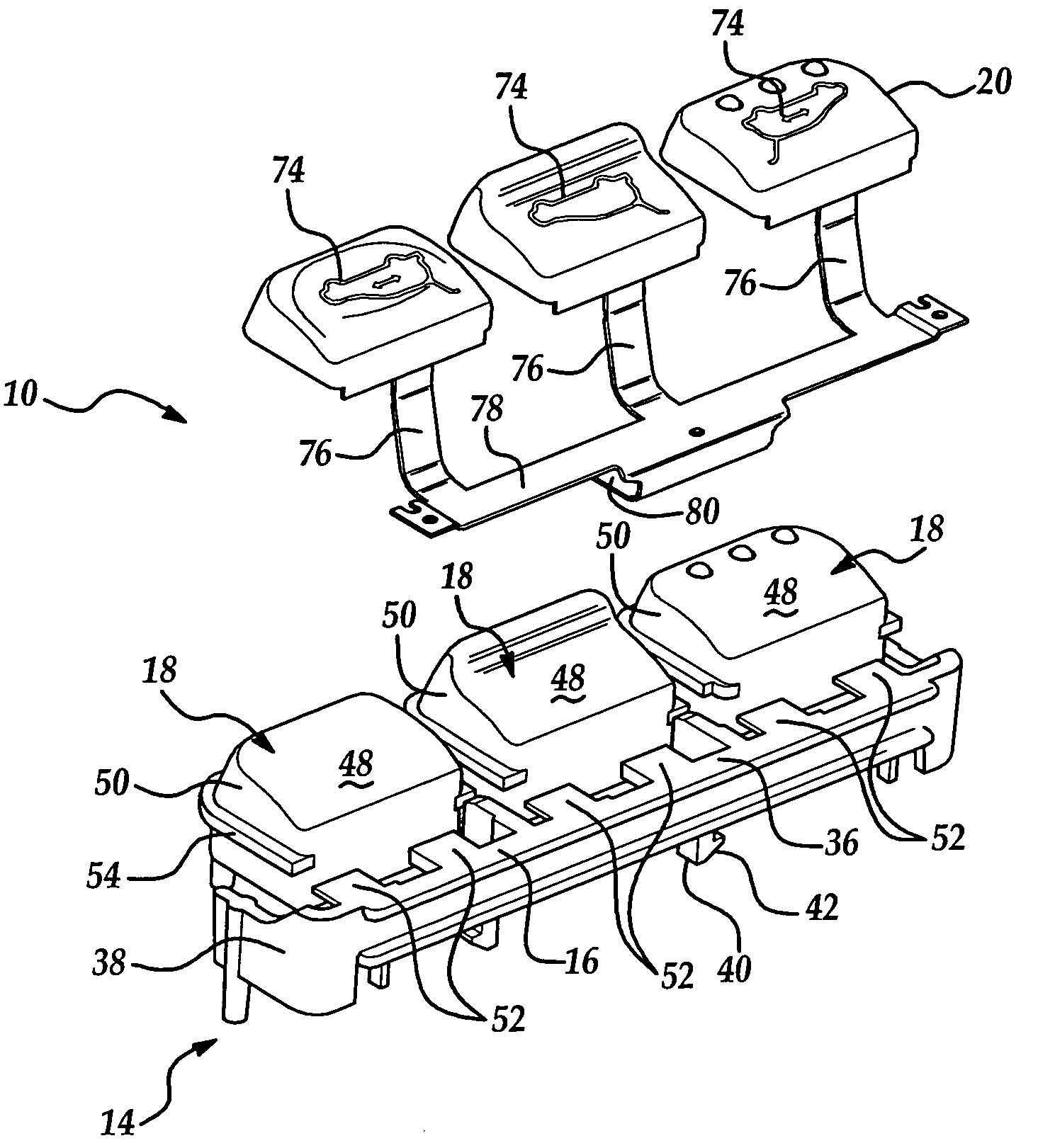
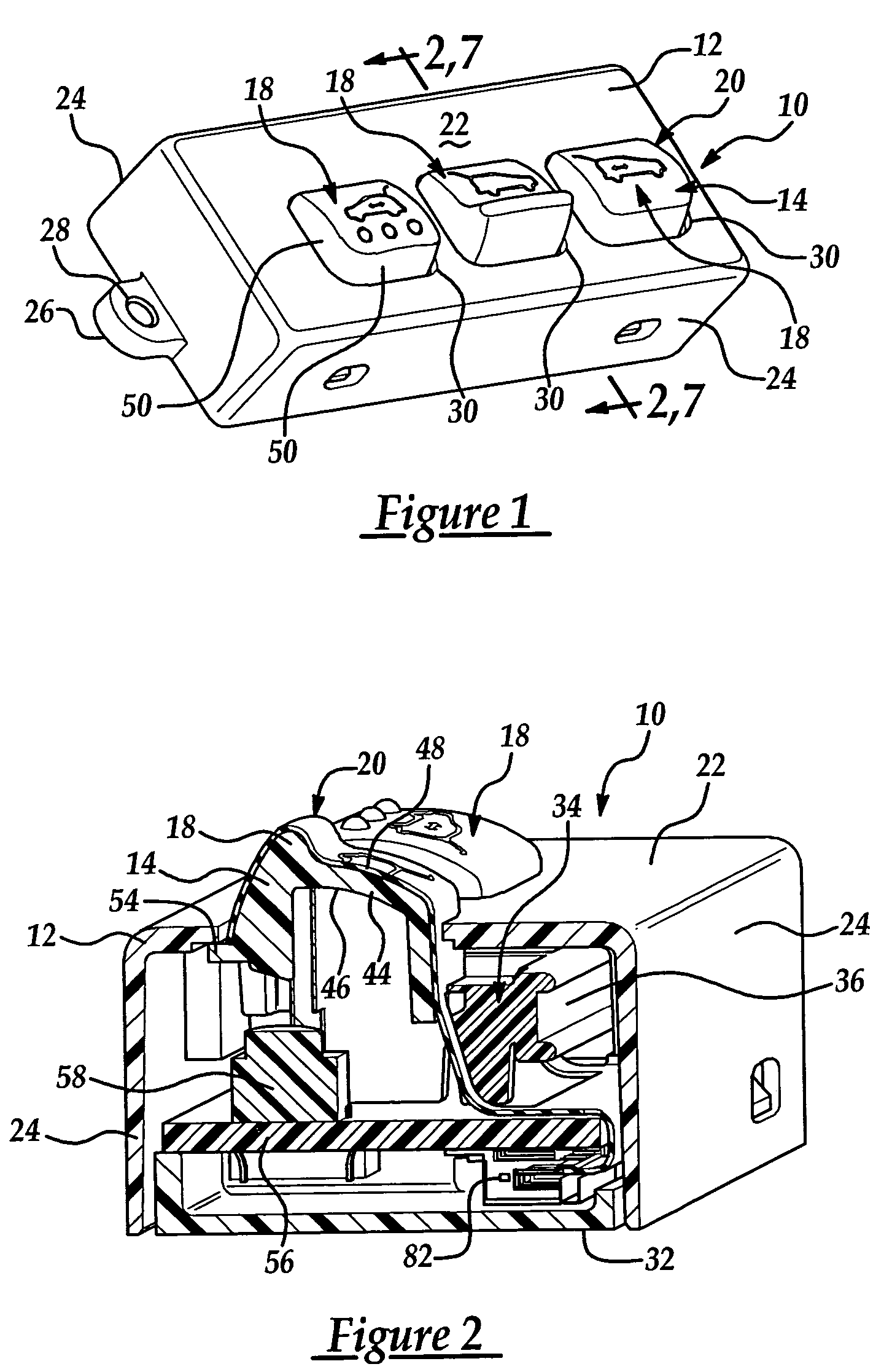
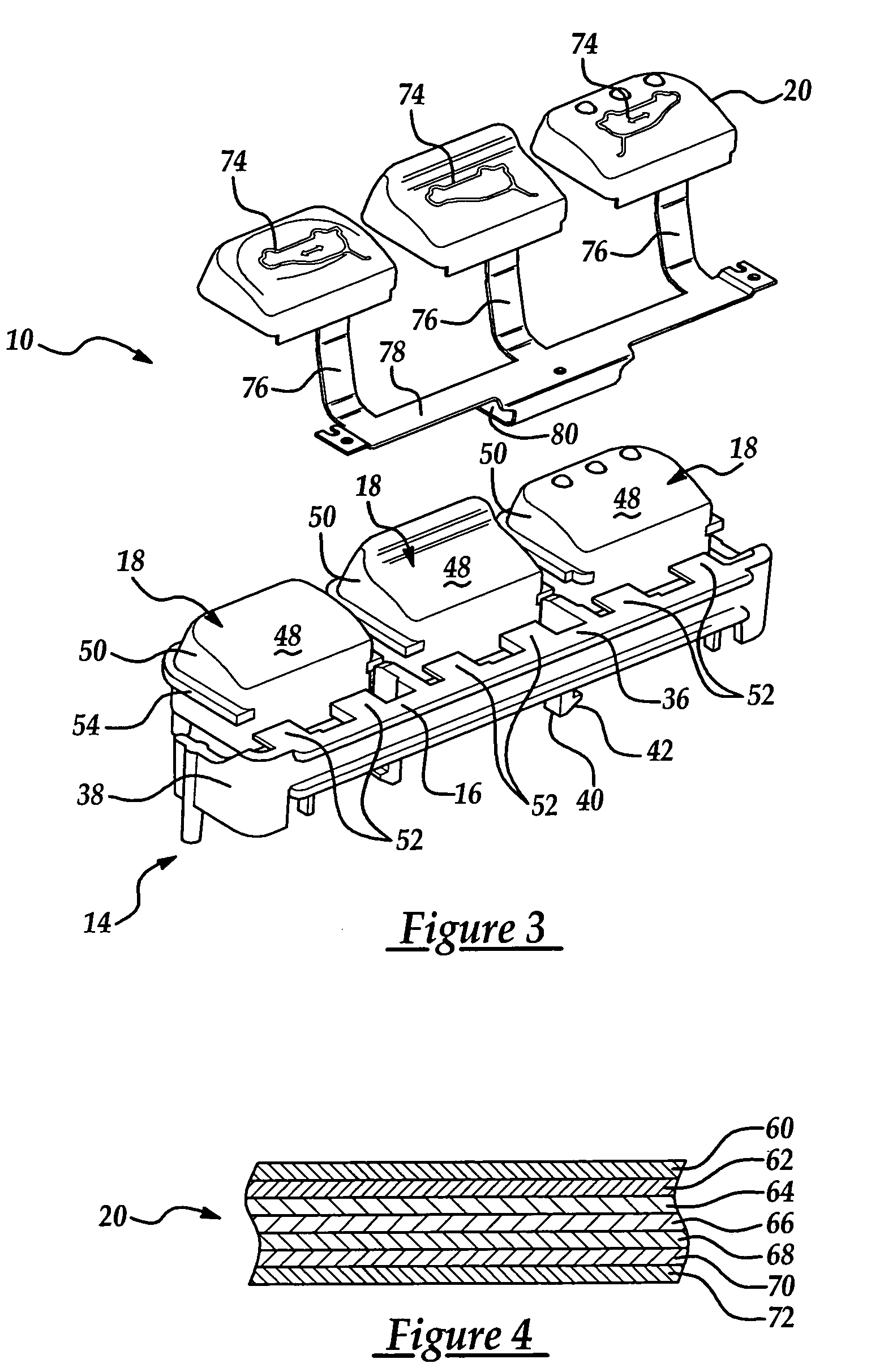
[0022]Referring now to the drawings, where like numerals are used to designate like structure throughout the figures, one embodiment of a control panel assembly of the present invention is generally illustrated at 10 in FIGS. 1–3. The control panel assembly 10 generally includes a support structure 12 and a button assembly 14 supported by the support structure 12. The button assembly 14 includes a frame member 16, at least one moveable button 18 supported by the frame member 16, and an electroluminescent (EL) film 20 disposed relative to the button 18 on an other surface of the button 18 as will be discussed in greater detail below. As will be described in greater detail, the control panel assembly 10 emits highly visible light such that the user can more easily control associated systems, and the control panel assembly 10 can be manufactured more efficiently than other comparable existing control panel assemblies.

[0023]As shown in FIGS. 1 and 2, the support structure 12 is box-lik...


PUM


Abstract

A control panel assembly including at least one moveable button defining an outer surface. The control panel assembly also includes an electroluminescent film operatively supported on the outer surface of the button such that the electroluminescent film is adapted for selectively emitting light from the outer surface of the button. A method for making the control panel assembly is also disclosed.

Description

BACKGROUND OF THE INVENTION[0001]1. Field of the Invention[0002]The present invention relates, generally, to a control panel assembly, and more particularly to a control panel assembly with a moveable illuminating button and a method of making the same.[0003]2. Description of the Related Art[0004]Many devices include control panels with stylized displays, dials, knobs and more. Control panel assemblies can also include buttons as a means for controlling associated systems. For instance, vehicle control panel assemblies can include buttons used to control the vehicle air conditioner, stereo, and more. When light levels are low, however, the user may not be able to properly see the control buttons.[0005]Partially in response to this need, control panel assemblies have been designed which include light sources for backlighting the buttons. Incandescent light bulbs, LEDs, and the like are supported near the back surface of the buttons to backlight the buttons and allow the user to see t...

Claims


Application Information

Patent Timeline
Patent Type & Authority Patents(United States)
IPC IPC(8): H01H9/00H01H13/83H01J1/02
CPCH01H13/83H01H2009/186H01H2207/004H01H2219/008H01H2231/026H01H2219/04H01H2219/046H01H2219/048H01H2221/016H01H2219/018
Inventor SCHMIDT, ROBERT M.PAGANO, LEONARD E.WRIGHT, JAMES B.
Owner LEAR CORP
Why Eureka
Try Eureka