
Turbine Blade With Recessed Tip

Inactive Publication Date: 2009-07-16
ZURICH ETH
View PDF8 Cites 9 Cited by
  • Summary
  • Abstract
  • Description
  • Claims
  • Application Information

AI Technical Summary

Benefits of technology

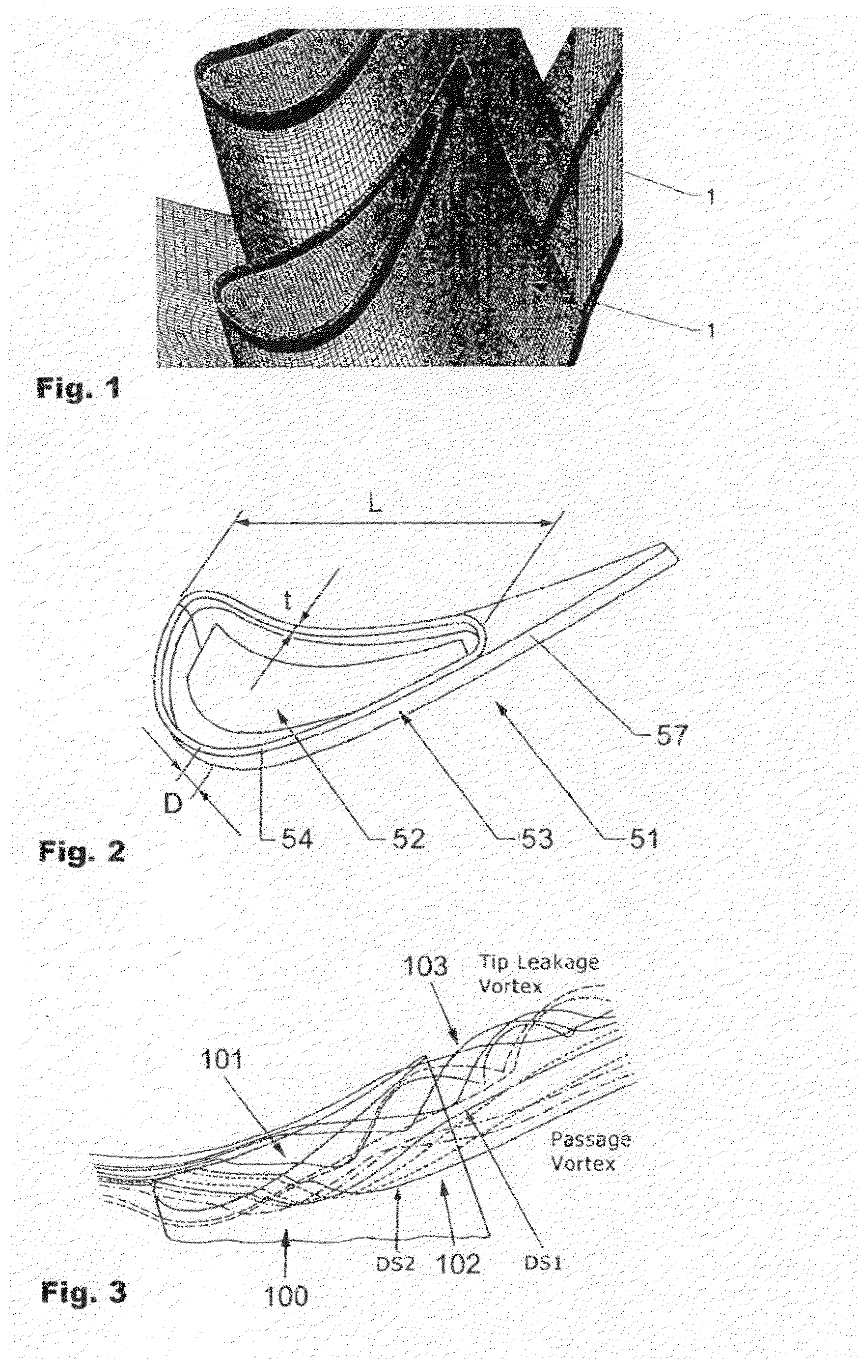
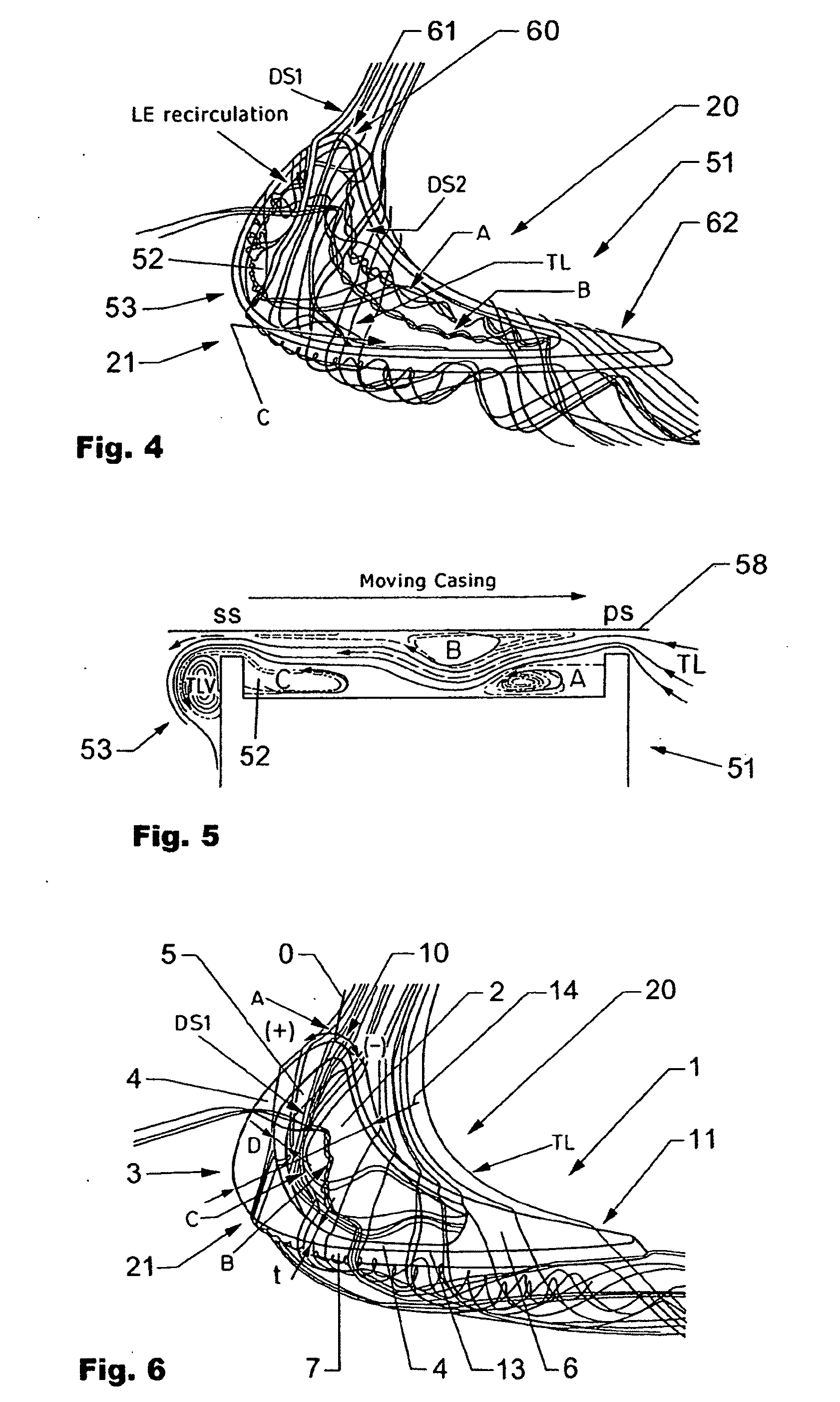
[0022]To overcome the problems known from the prior art a blade tip design is suggested with a recess in the blade tip instead of a simple flat blade tip. The recess (cavity) inside the blade tip acts as an aerodynamic seal which improves the performance of the turbine and / or reduces the heat load of the turbine tip, in that it takes influence on the flows distribution. Since material at the upper surface of the blade is moved to a lower radius from the axis of is rotation, blade root mechanical stresses can be lowered. Also in case of a tip rub, i.e. when the rotor blade touches the casing during rotation, only the thin cavity rim is damaged. Wear damage to the casing is also limited and since the purge holes for the blade tip cooling are located inside the cavity, the rubbing does not damage the outlet of the holes. Efficient cooling is hence assured even if rubbing occurs. Finally, the recess cavity may act as a labyrinth seal, which could be beneficial in reducing tip clearance mass flow.
[0047]Three-dimensional geometric profiling of blade tip recess cavities showing the above features keeps the advantages of non-profiled, constant rim thickness cavities, such as reduced rubbing surface area, cooling hole protection, lower mechanical stresses.

Problems solved by technology

Also in case of a tip rub, i.e. when the rotor blade touches the casing during rotation, only the thin cavity rim is damaged.

Method used


Image

  • Turbine Blade With Recessed Tip
  • Turbine Blade With Recessed Tip
  • Turbine Blade With Recessed Tip

Examples


Embodiment Construction

[0074]Subsequent embodiments of the invention are described in more detail. Similar features are in the different drawings marked with the same numbers.

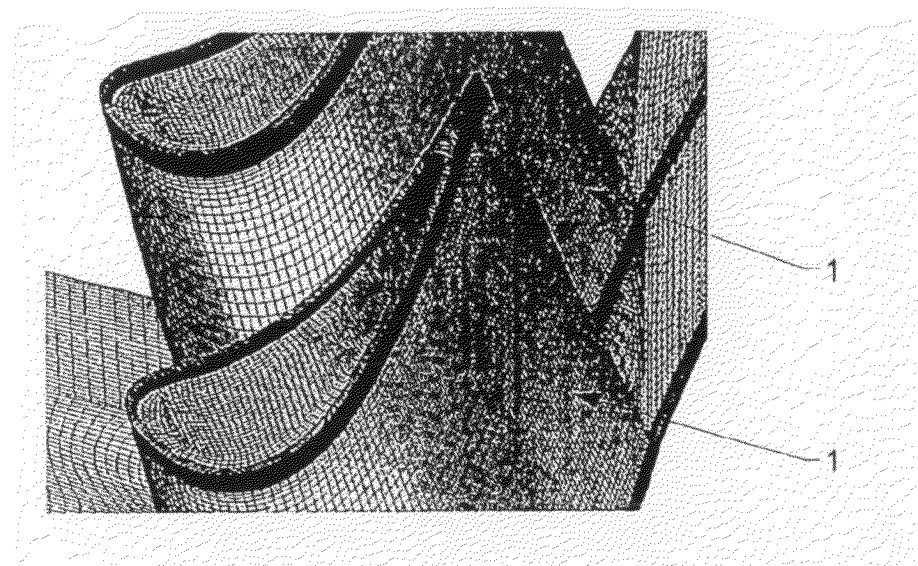
[0075]FIG. 1 shows a computer model of two turbine blades for numerical calculation of the behaviour of a recess arranged at the tip of a turbine blade.

[0076]The analytical models applied are in general based on a numerical grid (mesh) of a turbine blade 1. The numerical grids used were generated with an in-house developed grid generator called MELLIP. A multi block structured grid generator uses a two dimensional NURBS library as input data to mesh the computational domain boundaries. Using a set of geometrical transformations the interior block boundaries are defined according to the intended grid topology. High grid quality, i.e. smooth gridlines, limited aspect ratio, skewness and cell to cell ratios are achieved using both non linear interpolation algorithms with flexible clustering specification and two dimensional Poisson type...


PUM


Abstract

A turbine blade (1) with a side surface (7) having an aerodynamic profile. The turbine blade (1) further comprises an end surface (6) and is mounted in a turbine, whereby the end surface (6) is delimited by a gap from a casing (8) of the turbine. The end surface (6) comprises a recess (2) which is shaped such that it acts as an improved aerodynamic seal.

Description

FIELD OF THE INVENTION[0001]The invention lays in the field of turbine blades for highly loaded axial rotor turbines as e.g. used in aero engines or for power generation.DESCRIPTION OF THE ART[0002]In axial turbine the tip clearance flow occurring in rotor blade rows is responsible for about one third of the aerodynamic losses in the blade row and in many cases is the limiting factor for the blade lifetime.[0003]The tip leakage vortex forms when the leaking fluid crosses the gap between the rotor blade tip and the casing from pressure to suction side and rolls up into a vortex on the blade suction side. The flow through the tip gap is both of high velocity and high temperature, with the heat transfer to the blade from the hot fluid being very high in the blade tip area. In order to avoid blade tip burnout and a failure of the machine, blade tip cooling is commonly used.[0004]The tip clearance flow has been investigated recently with a number of contributions in the open literature. ...

Claims


Application Information

Patent Timeline
IPC IPC(8): F01D5/14
CPCF01D5/20F05D2240/55F01D11/122
Inventor MISCHO, BOBABHARI, REZABEHR, THOMAS
Owner ZURICH ETH
Learn More