
Electromechanical Transducer

a transducer and electromechanical technology, applied in the direction of microelectromechanical systems, electrical apparatus, machines/engines, etc., can solve the problems of large displacement, high mechanical force, and high mechanical force of actuators at low voltage, and reduce the size of classical engineering designs only limited potential, and strain on crystals

Inactive Publication Date: 2009-07-16
CZECH TECH UNIV IN PRAGUE
View PDF1 Cites 3 Cited by
  • Summary
  • Abstract
  • Description
  • Claims
  • Application Information

AI Technical Summary

Benefits of technology

[0042]2) The size of the particles is optimal to maximize the change of density of the potential energy of van der Waal's attraction.

Problems solved by technology

However, the actuators have to induce needful and often high mechanical forces and large displacements at low voltages and currents.
Mere size reduction of the classical engineering designs has only limited the potential and is incorrect in essence.
Applying an electrical field causes the deformation of the dipoles, leading to a strain on the crystal.
Contemporary, rather high voltages are not directly compatible with voltages in microelectronics.
When conducting an electrical current, heat is generated because of Joule losses.
During the cooling process, rather slow spontaneous processes remove heat.
The disadvantage of low efficiency below 2% is determined by thermodynamics.
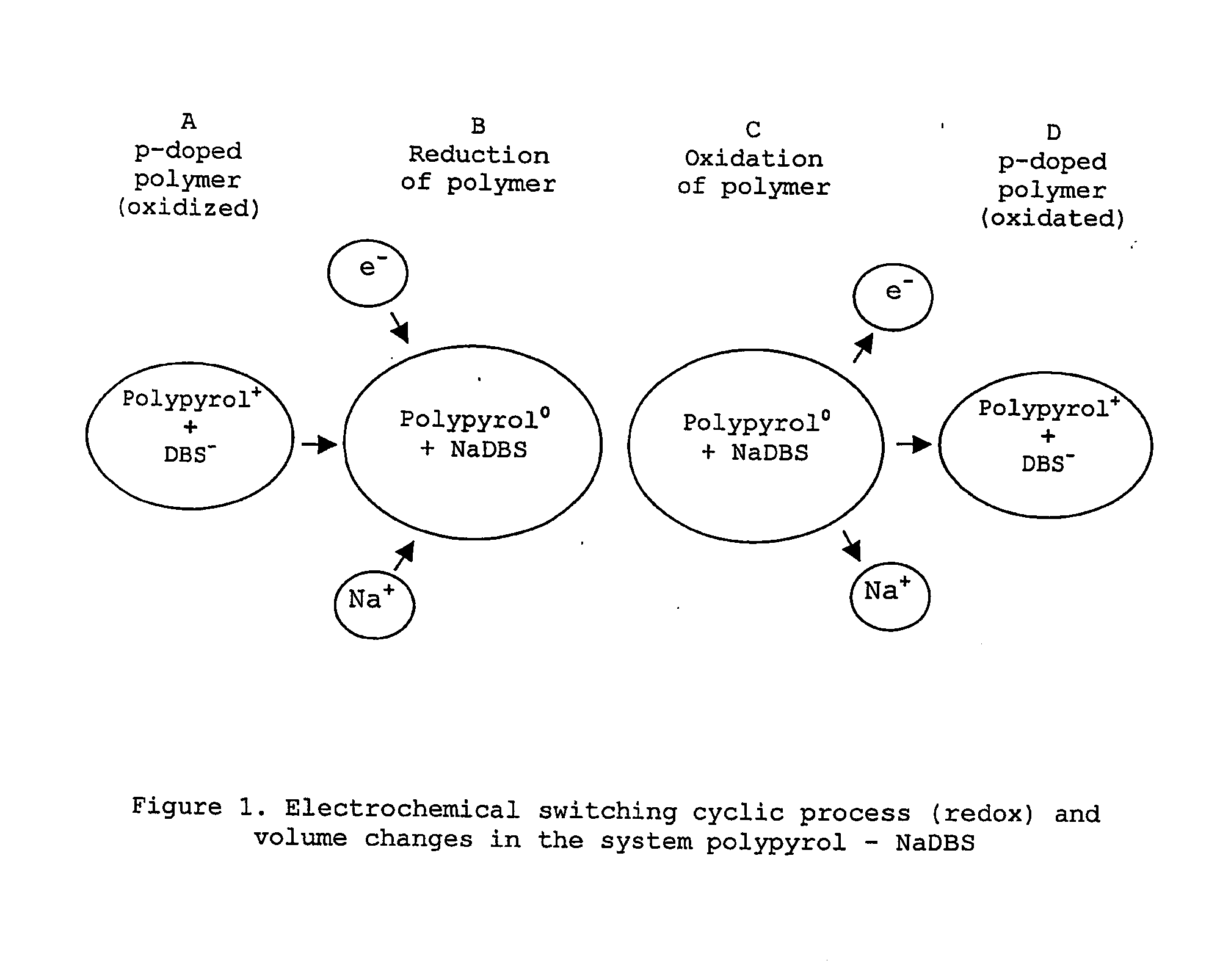
Because of their large size, DBS− anions are immobile and cannot diffuse easily out of the polymer.
The low linear strain of the conductive polymer impedes the construction of the effective linear actuators working in the same way as natural muscles.
However, the problem with a small low linear strain remains to be solved.
The common principal disadvantage of biomolecular motors is their limited lifetime in vitro, and the narrow range of environmental conditions that they are able to tolerate.
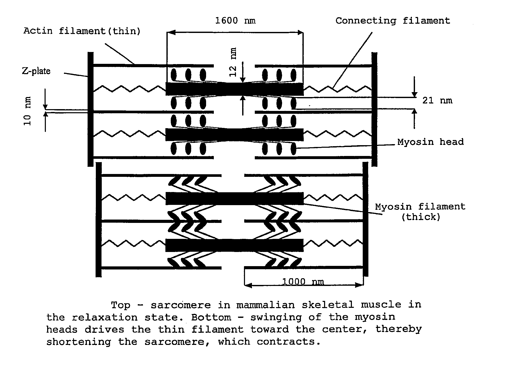
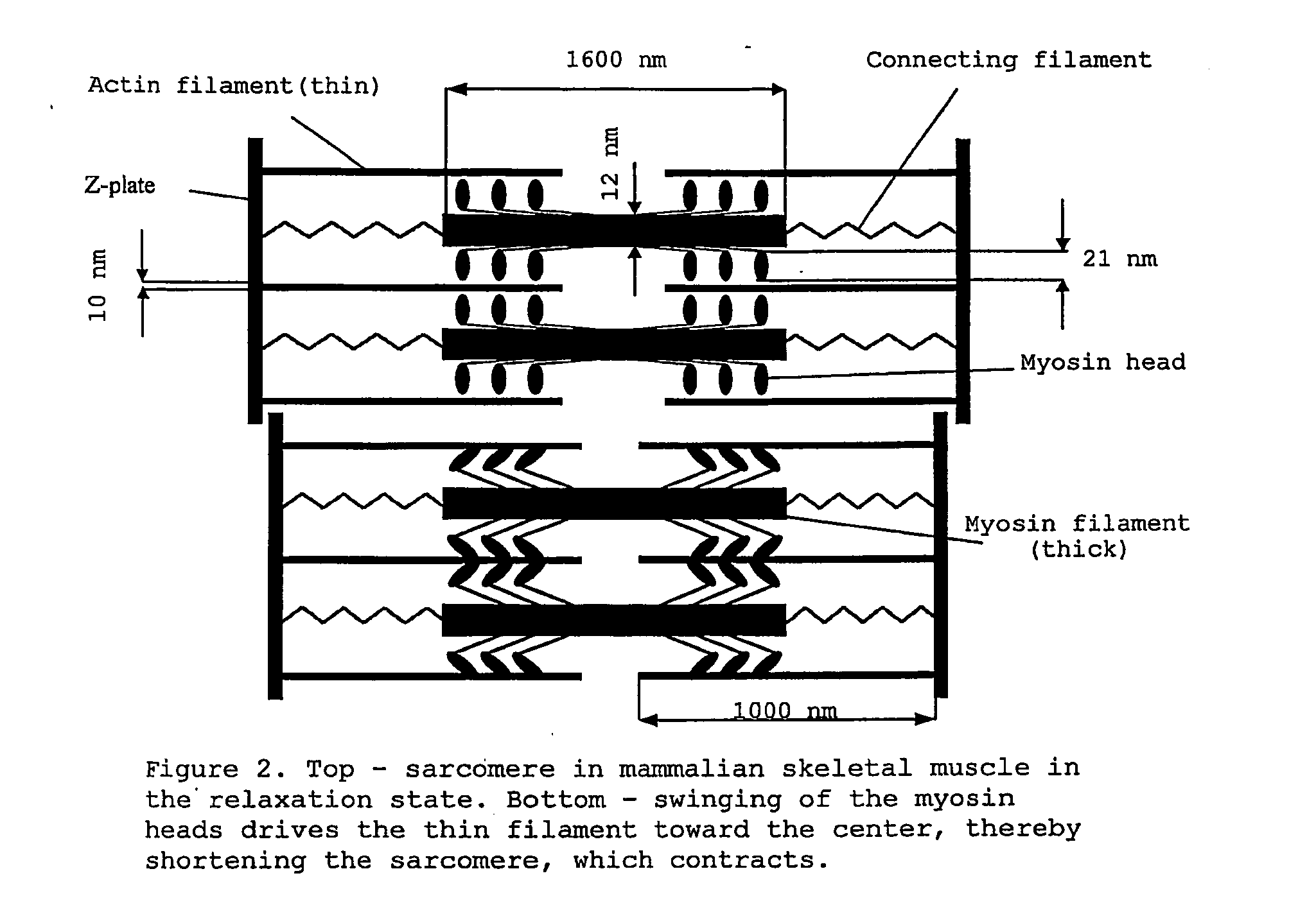
Unfortunately, scientific explanations of the swinging mechanism of the heads are rather confused.
However, several questions remain unanswered.

Method used


Image

  • Electromechanical Transducer
  • Electromechanical Transducer
  • Electromechanical Transducer

Examples


Embodiment Construction

OF THE INVENTION

[0095]Size of Particles—Equation (7)

[0096]The optimal radius of the spherical polymer particles in lukewarm water (H=5.10−21 J, T=310 K), with an utmost approach d0=0.424 nm (the thickness of two layers of ions Ca2+)

R*=27kTd0H=27×1.38×10-23×310×0.424×10-95×10-21=9.80×10⁻⁹m=9.8nm

[0097]Utmost van der Waal's Energy Change—Equation (8)

[0098]The relevant internal energy change for the space filling Φ=0.185 (spherical particles in the hcp lattice, DH / DC=0.5, equation (7))

ɛ*=Φπ67(kT)2(2Hd0)3=-0.185π×67(k×310)2(2×5×10-210.424×10⁻⁹)3=-150.652kJm-3

[0099]Complex Interaction Energy Change—Equation (9)

[0100]FIG. 8 depicts the interaction energy in dependence on the mutual distance of the spherical nanoparticles with radius R=10.5 nm, the relative permittivity in a water medium εR˜80 and the variable concentration of divalent ions according to the parameters on the graph.

[0101]Particles in the relaxation state are at the cations lower concentration 2E24 m−3, the spherical particle...


PUM


Abstract

The function of the key element of the SMA, is based on a mutual alternating slipping of two systems of filaments. Its contraction is caused by the attractive effect of van der Waal's forces between the functional particles among the filaments. The relaxation is attained through the repulsive effect of the electrostatic repulsive forces between the functional particles. The alternating change of ionic concentration in the area of the particles results in the alternating function of van der Waal's attraction and repulsive electrostatic forces. The size and material of the particles, their configuration and working temperature must be specifically optimized. The total contraction of the key element results from the summation of its partial contractions. The total force and contraction of the SNA result from the summation of the key elements in the parallel (collateral) and / or serial (linear ranked) arrangements, respectively. Large compound actuators with high performance can be built from key elements using the modular design.

Description

TECHNICAL FIELD[0001]An electromechanical transducer is a device which transforms electrical energy into mechanical work (e.g. as the product of generated force and shift). Transducers are applied extensively in all spheres of our environment. They are well established in classical engineering as electrical motors, electromagnets, electro-mechanical systems with pneumatic or hydraulic cylinders, etc. In microelectronics, the electromechanical transducers are called actuators that link the information-processing component of electronic control circuitry with technical processes. They are exploited in a number of applications including medical, space, robotic, microelectronic machines, etc., and can be found in CD players and cameras, washing machines, heating and air-conditioning systems, machining equipment, automobiles, boats and aircraft and even respiratory equipment and artificial limbs.BACKGROUND OF THE INVENTION[0002]The methods of electrical energy transformation into the for...

Claims


Application Information

Patent Timeline
Patent Type & Authority Applications(United States)
IPC IPC(8): H02N11/00
CPCB81B3/0021H02N11/006F03G7/06B81B2203/051
Inventor BOUDA, VACLAV
Owner CZECH TECH UNIV IN PRAGUE
Learn More