
CPAP system and method of use

Inactive Publication Date: 2009-07-09
SHORT MICHAEL J
View PDF2 Cites 25 Cited by
  • Summary
  • Abstract
  • Description
  • Claims
  • Application Information

AI Technical Summary

Benefits of technology

[0013]A specially designed air treatment device is shown for use with a CPAP system in order to greatly reduce the risk of respiratory infection for patients being treated for sleep apnea.

Problems solved by technology

Since a continuous positive air flow is supplied to the OSA patient, the patient becomes particularly susceptible to respiratoy infections.

Method used


Image

  • CPAP system and method of use
  • CPAP system and method of use
  • CPAP system and method of use

Examples


Embodiment Construction

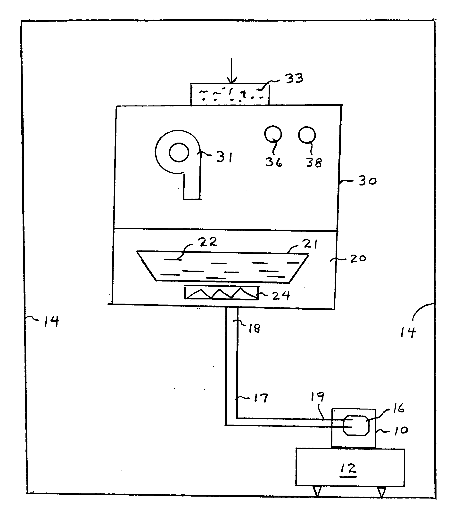
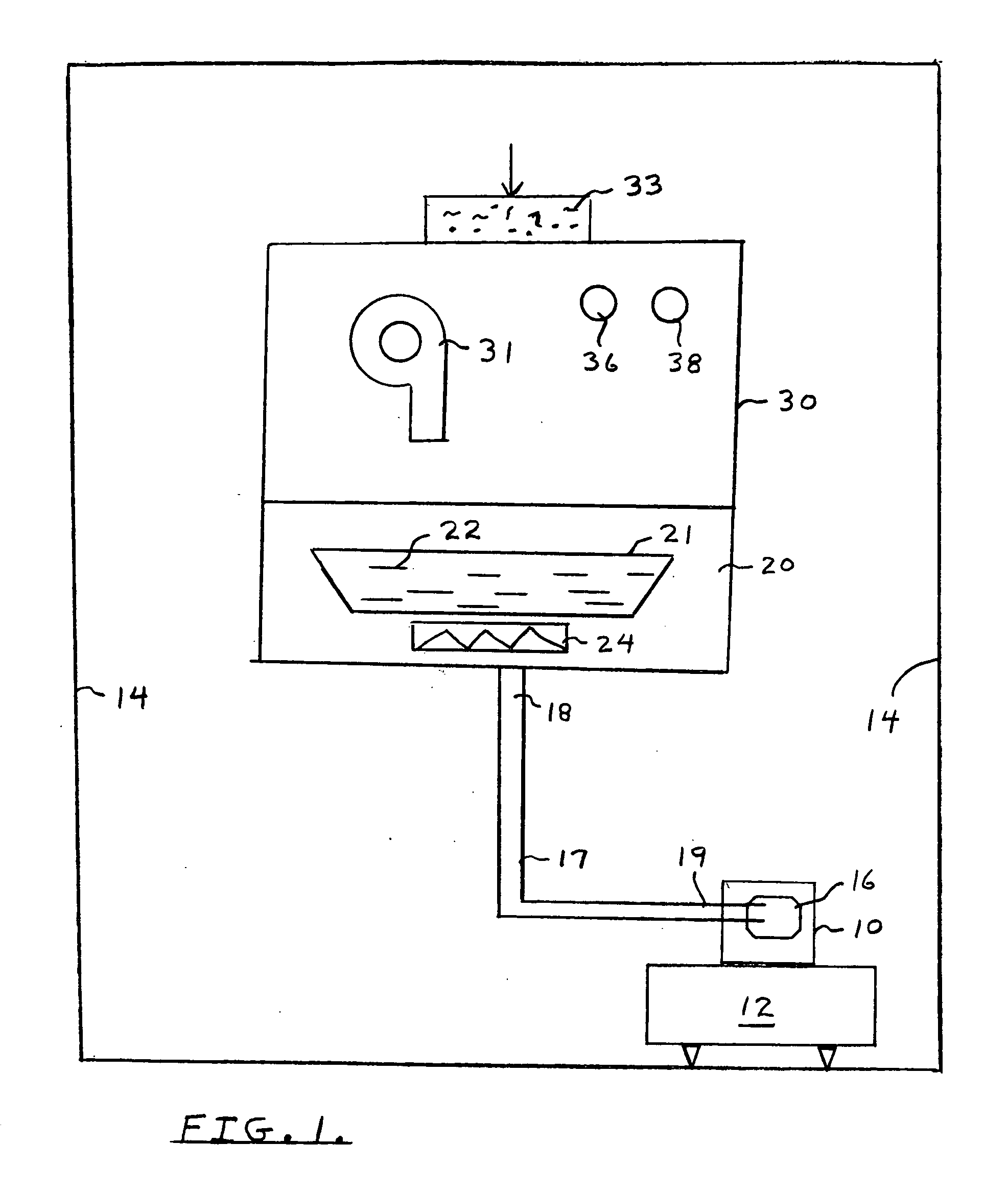
[0022]Referring to the Prior Art drawings of FIGS. 1 and 2, a sleep apnea patient is indicated schematically at numeral 10 as on bed 12 in a surrounding room 14.

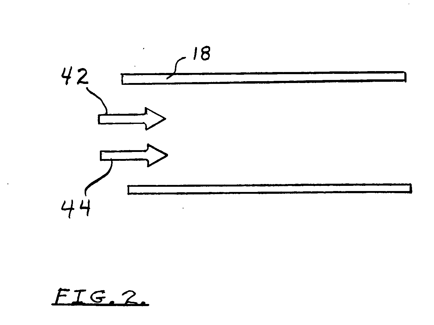
[0023]Patient 10 has a mask 16. A positive pressure air flow is supplied to the mask 16 by means of line 17. Line 17 has a right end 19 connected to the mask and a left end 18 connected to a combined CPAP and humidifier system.

[0024]The humidifier is indicated at numeral 20 and includes a water tray 21 with water 22 container therein. An electric heating element to vaporize water is shown schematically at numeral 24.

[0025]A Continuous Positive Airway Pressure(CPAP) device 30 is indicated as having a blower 31 as an essential part of the system. An air filter 33 is also schematically shown.

[0026]Speed control elements for the blower are indicated at numerals 36 and 38.

[0027]Various other CPAP system components and uses are shown in the cited prior art patents.

[0028]It is important to realize that obstructive sleep apnea patie...


PUM


Abstract

A system and method for treating obstructive sleep apnea(OSA) by means of a Continuous Positive Airway Pressure(CPAP) system in which is included an ultra-violet light source to remove bacteria and contaminants which may cause respiratory infection in a patient being treated. The ultravoilet light source is contained in a specially designed chamber comprising aluminum or equivalent suitable materials. The ultraviolet chamber is positioned directly downstream of a humidification unit and includes specially positioned baffles to protect connecting elements and other system components from any possible damage.

Description

BACKGROUND AND OBJECTS OF THE INVENTION[0001]The present invention is generally related to the CPAP arts which stands for Continuous Positive Airway Pressure systems and methods of use. Such are utilized for the treatment of Obstructive Sleep Apnea(OSA).[0002]CPAP devices have proven to be very successful in the effective treatment of OSA patients.[0003]A typical CPAP device includes filters which are intended to reduce the risk of respiratory infection for OSA patients. A typical instruction manual for a CPAP system encourages regular filter change. If a humidifier is included in the system, water should be changed on a daily basis to prevent stagnation of the humidifying moisture.[0004]Since a continuous positive air flow is supplied to the OSA patient, the patient becomes particularly susceptible to respiratoy infections. Such are of course very serious matters so it becomes a critical matter to supply the cleanest air possible to the OSA patient.[0005]Accordingly, it is an objec...

Claims


Application Information

Patent Timeline
IPC IPC(8): A61M16/00
CPCA61M16/0066A61M16/1055A61M16/109A61M2205/053A61M2206/14A61M16/16
Inventor SHORT, MICHAEL J.
Owner SHORT MICHAEL J
Learn More