
Tracking temporal use associated with cache evictions

a technology of cache eviction and tracking temporal use, which is applied in the field of microprocessors, can solve the problems of affecting the overall performance of the system,

Inactive Publication Date: 2009-07-02
INTEL CORP
View PDF2 Cites 13 Cited by
  • Summary
  • Abstract
  • Description
  • Claims
  • Application Information

AI Technical Summary

Benefits of technology

The present invention relates to a method and apparatus for tracking temporal use associated with cache evictions to reduce allocations in a victim cache. The invention involves tracking access data for sets of instructions stored in the instruction cache until the access data reaches a predetermined threshold condition. When an entry is evicted from the cache, a determination is made whether to allocate entry storage in the victim cache. The invention helps filter out a significant number of victim cache allocations and reduces the impact on processor performance.

Problems solved by technology

Therefore, deallocation or eviction of the line, in particular from an instruction cache, cannot take place until all instructions from that line are no longer being processed in the execution pipeline.
If too many instruction lines are evicted from the instruction cache prior to a victim cache deallocation, the victim cache can fill up resulting in unwanted stalls for the execution pipeline.
Furthermore, insertion of numerous special micro-operations into the execution pipeline may cause further degradation to overall performance.
Especially for heavy workloads of new instructions where poorly predicted branching may occur, the performance degradation may be significant.
Increasing the victim cache size may reduce the number of stalls, but may not improve upon the numerous special micro-operations inserted into the execution pipeline.
Moreover an increased victim cache size comes only at a tradeoff of reducing available area for other circuitry and potentially increasing critical timing paths.
To date, other alternative solutions have not been adequately explored.

Method used


Image

  • Tracking temporal use associated with cache evictions
  • Tracking temporal use associated with cache evictions
  • Tracking temporal use associated with cache evictions

Examples


Embodiment Construction

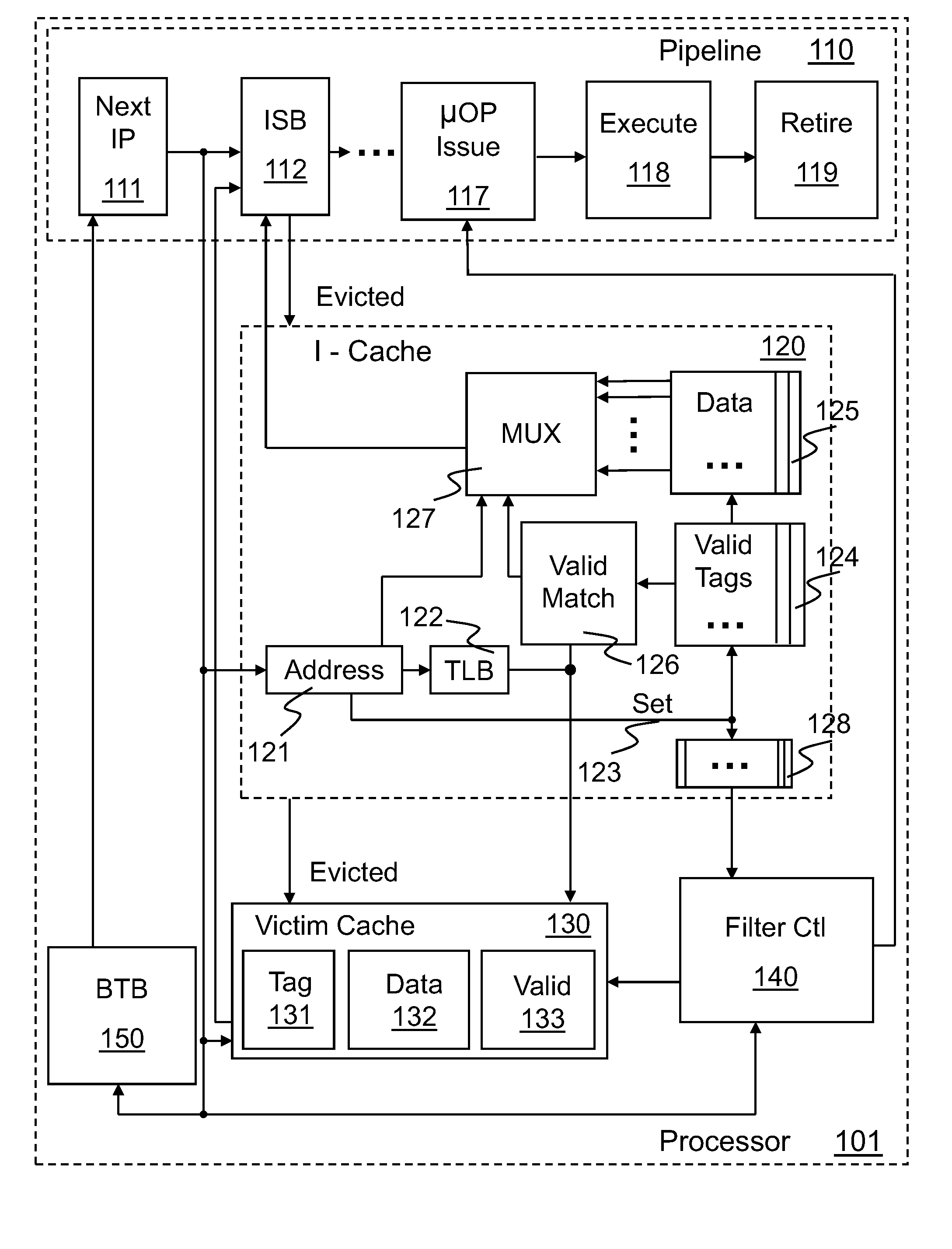
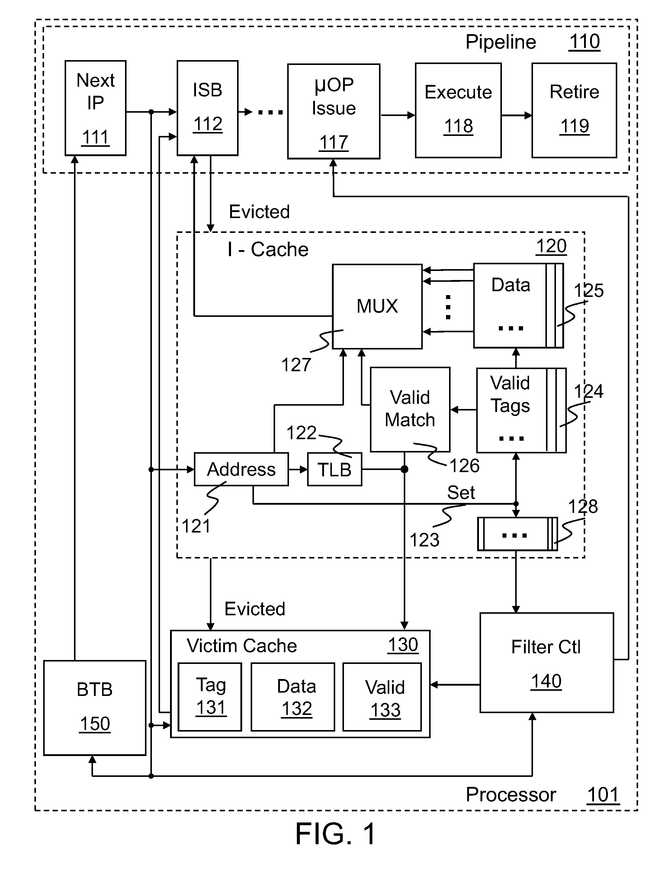
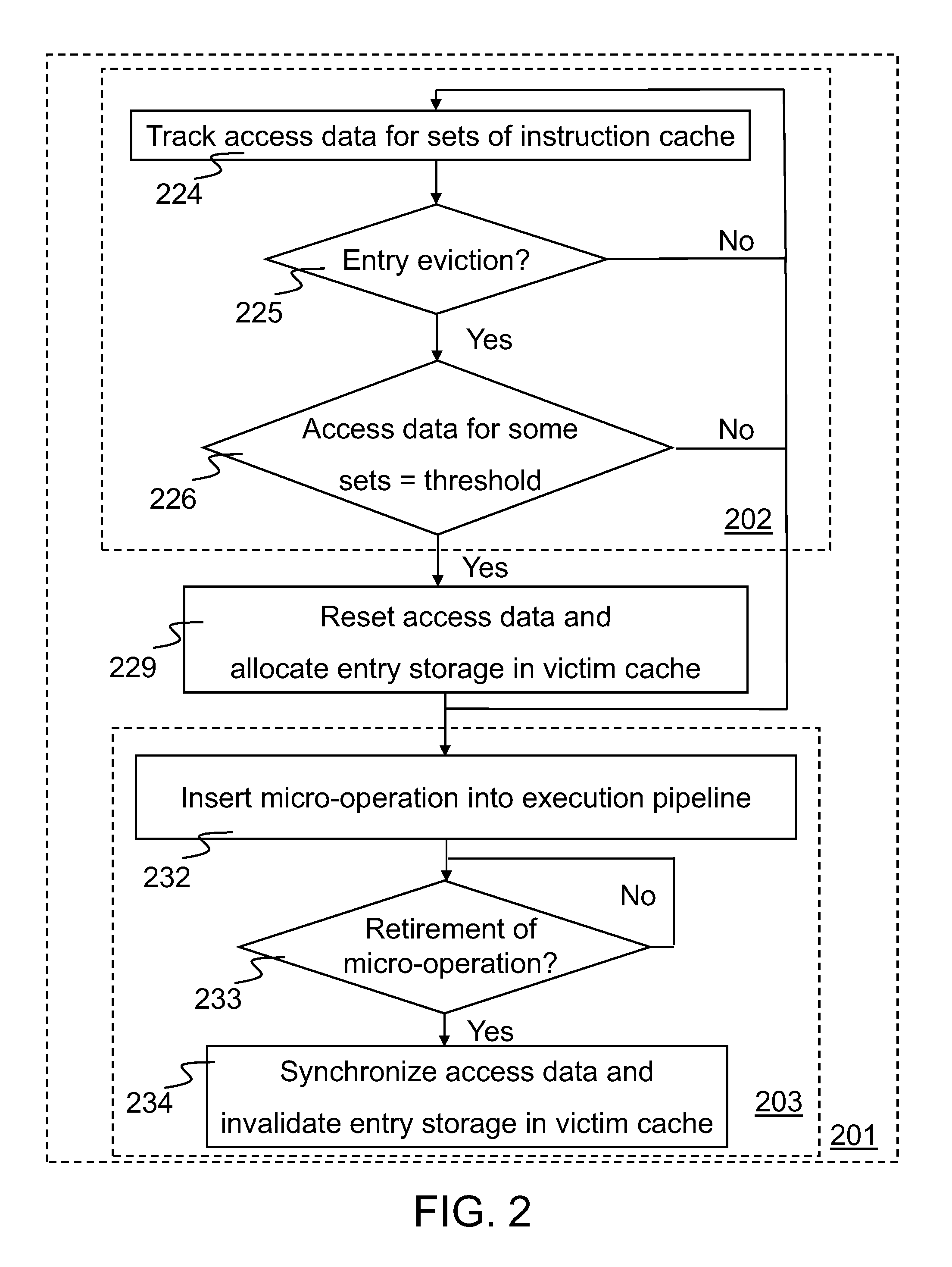
[0012]A method and apparatus for tracking temporal use associated with cache evictions to reduce the number of allocations in a victim cache is disclosed herein. For one embodiment, access data for a number of sets of instructions stored in an instruction cache is tracked at least until the data for one or more of those sets reaches a predetermined threshold condition. Upon eviction of an entry from the instruction cache, a determination whether to allocate entry storage in the victim cache depends in part on the access data for sets reaching the predetermined threshold condition. If it is determined that the threshold condition has not been met, then the entry may be evicted from the instruction cache without requiring victim cache allocation. If it is determined in the affirmative to allocate the entry storage, a micro-operation can be inserted into the execution pipeline in part to synchronize the access data for all the sets. Then upon retirement of the micro-operation from the ...


PUM


Abstract

A method and apparatus for tracking temporal use associated with cache evictions to reduce allocations in a victim cache is disclosed. Access data for a number of sets of instructions in an instruction cache is tracked at least until the data for one or more of the sets reach a predetermined threshold condition. Determinations whether to allocate entry storage in the victim cache may be made responsive in part to the access data for sets reaching the predetermined threshold condition. A micro-operation can be inserted into the execution pipeline in part to synchronize the access data for all the sets. Upon retirement of the micro-operation from the execution pipeline, access data for the sets can be synchronized and / or any previously allocated entry storage in the victim cache can be invalidated.

Description

FIELD OF THE DISCLOSURE[0001]This disclosure relates generally to the field of microprocessors. In particular, the disclosure relates to tracking temporal use associated with cache evictions.BACKGROUND OF THE DISCLOSURE[0002]In modern processors, execution pipelines are often used. Instructions are provided to the front end of the pipeline by various arrays, buffers, and caches. Such front-end arrays that contain instruction lines, may also includes self-modifying code (SMC) bits to detect which instruction lines may have been overwritten by self-modifying or cross-modifying code.[0003]It will be appreciated that for correct functionality considerations such as processor inclusion, any instruction line that has been delivered into the execution pipeline may later need to be re-delivered in an unmodified state. Therefore, deallocation or eviction of the line, in particular from an instruction cache, cannot take place until all instructions from that line are no longer being processed...

Claims


Application Information

Patent Timeline
Patent Type & Authority Applications(United States)
IPC IPC(8): G06F12/08
CPCG06F12/123
Inventor SMITH, PETER J.EKPANYAPONG, MONGKOLBALIGA, HARIKRISHNAKIM, ILHYUN
Owner INTEL CORP
Learn More