
Method and system for multiple branch paths in a microprocessor

Inactive Publication Date: 2005-03-31
INTEL CORP
View PDF2 Cites 17 Cited by
  • Summary
  • Abstract
  • Description
  • Claims
  • Application Information

AI Technical Summary

Problems solved by technology

However, it takes many processing cycles to clear the processing units of the micro-operations (uops) related to the mispredicted branch.

Method used


Image

  • Method and system for multiple branch paths in a microprocessor
  • Method and system for multiple branch paths in a microprocessor
  • Method and system for multiple branch paths in a microprocessor

Examples


Embodiment Construction

[0010] Embodiments of a system and method for multiple branch paths in a microprocessor are described. In the following description, numerous specific details are set forth. However, it is understood that embodiments of the invention may be practiced without these specific details. In other instances, well-known circuits, structures and techniques have not been shown in detail in order not to obscure the understanding of this description.

[0011] Reference throughout this specification to “one embodiment” or “an embodiment” means that a particular feature, structure, or characteristic described in connection with the embodiment is included in at least one embodiment of the invention. Thus, the appearances of the phrases “in one embodiment” or “in an embodiment” in various places throughout this specification are not necessarily all referring to the same embodiment. Furthermore, the particular features, structures, or characteristics may be combined in any suitable manner in one or mo...


PUM


Abstract

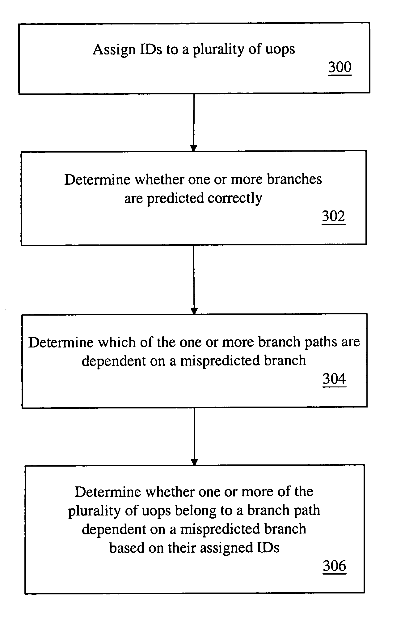
A method and system for multiple branch paths in a microprocessor is described. The method includes assigning an identification number (ID) to each of a plurality of micro-operations (uops) to identify a branch path to which the uop belongs, determining whether one or more branches are predicted correctly, determining which of the one or more branch paths are dependent on a mispredicted branch, and determining whether one or more of the plurality of uops belong to a branch path that is dependent on a mispredicted branch based on their assigned IDs.

Description

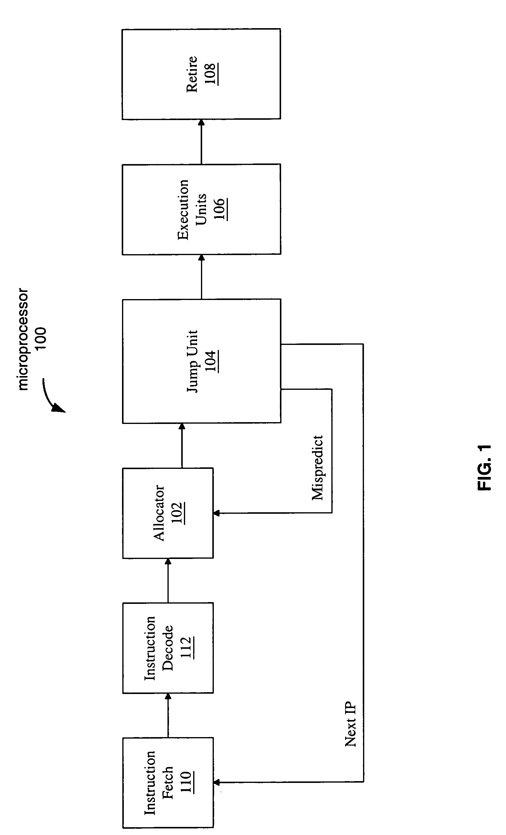
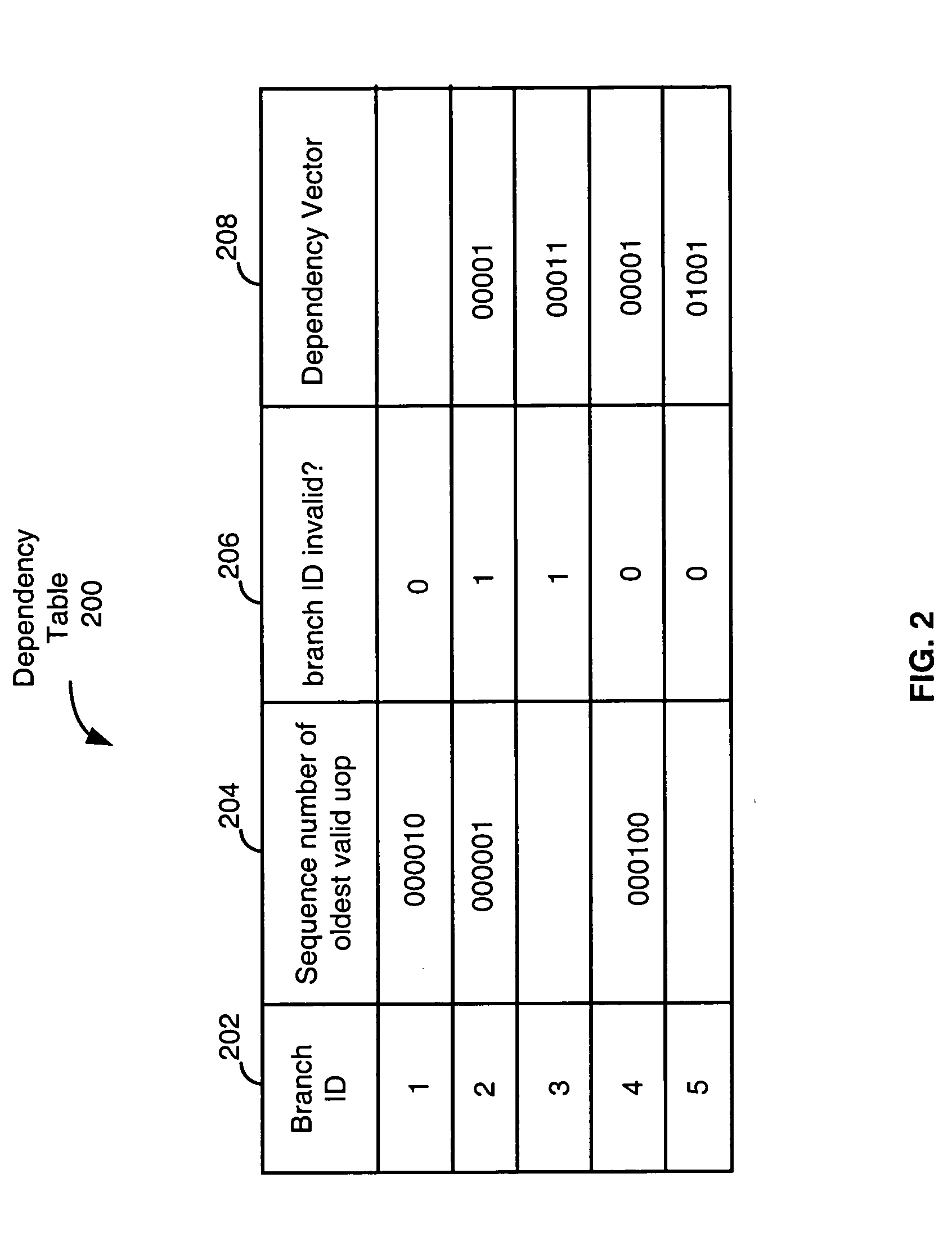
BACKGROUND [0001] 1. Technical Field [0002] Embodiments of the invention relate to the field of microprocessors, and more specifically to multiple branch paths in a microprocessor. [0003] 2. Background Information and Description of Related Art [0004] In current processors, branches are checked in a dedicated jump unit. This jump unit checks the branch direction and prediction. If a branch is not predicted correctly, a pipeline clear occurs, which directs the front end units of the processor to the correct instruction pointer. However, it takes many processing cycles to clear the processing units of the micro-operations (uops) related to the mispredicted branch. BRIEF DESCRIPTION OF DRAWINGS [0005] The invention may best be understood by referring to the following description and accompanying drawings that are used to illustrate embodiments of the invention. In the drawings: [0006]FIG. 1 is a block diagram illustrating one generalized embodiment of a microprocessor incorporating the...

Claims


Application Information

Patent Timeline
IPC IPC(8): G06F9/00G06F9/318G06F9/38
CPCG06F9/3017G06F9/3804G06F9/3861G06F9/3842G06F9/3844G06F9/3806
Inventor JOURDAN, STEPHANHAMMARLUND, PERSODANI, AVINASHALLEN, JAMESMCKEEN, FRANCISMICHAUD, PIERRE
Owner INTEL CORP
Learn More