
Multi-primary LED collimation optic assemblies

Active Publication Date: 2009-07-02
LIGHTING SCI GROUP
View PDF12 Cites 47 Cited by
  • Summary
  • Abstract
  • Description
  • Claims
  • Application Information

AI Technical Summary

Benefits of technology

[0012]Multi-primary LED collimation optic assemblies are presented which are able to produce a light beam having improved collimation and color uniformity compared to conventional assemblies. Light emitted by the LEDs passes through an optical assembly which may include the optical features of a spline patch inner lens, at least two lenslet arrays, a rippled reflector, and at least one secondary collimation lens. The spline patch inner lens, TIR lens and at least one lenslet array are shaped to match the placement of the LEDs within the light engine. Surface details of the optical components improve the collimation, efficiency and color uniformity of the light passing through the light guide. A second embodiment of the optical assembly includes a ribbed light guide and a collimation reflector.

Problems solved by technology

However, light from the individual LEDs historically has been difficult to collimate to a narrow beam, thereby producing a composite light having poor color uniformity.
LED spacing within the light engine limits the minimum distance at which the light engine can be located from the target of its illumination, because too small a distance from the target of illumination produces poor composite color uniformity illumination of a close-in target.
Color mixing improves as LED spacing is reduced, but equipment or speed of manufacture limit how close together the LEDs may be placed, causing conventional multi-colored light engines like that shown in FIG. 1 to suffer from poor color mixing.
Light engines are designed with the LEDs spaced relatively widely apart for improved heat dissipation, thereby causing poor color mixing.
Viewers may see the poor color mixing as changes in the perceived light color from the light engine when viewed from different viewing angles.
Second, fabrication machines and techniques may limit the minimum distance the LED die can be placed on the substrate.
This separation of the colors is not desirable for some applications.
The conventional solutions to collimating multi-primary emitters produce a more homogeneous color uniformity at the expense of a wider beam width, and therefore the conventional solutions cannot separately and simultaneously optimize both color uniformity and beam width.

Method used


Image

  • Multi-primary LED collimation optic assemblies
  • Multi-primary LED collimation optic assemblies
  • Multi-primary LED collimation optic assemblies

Examples


Embodiment Construction

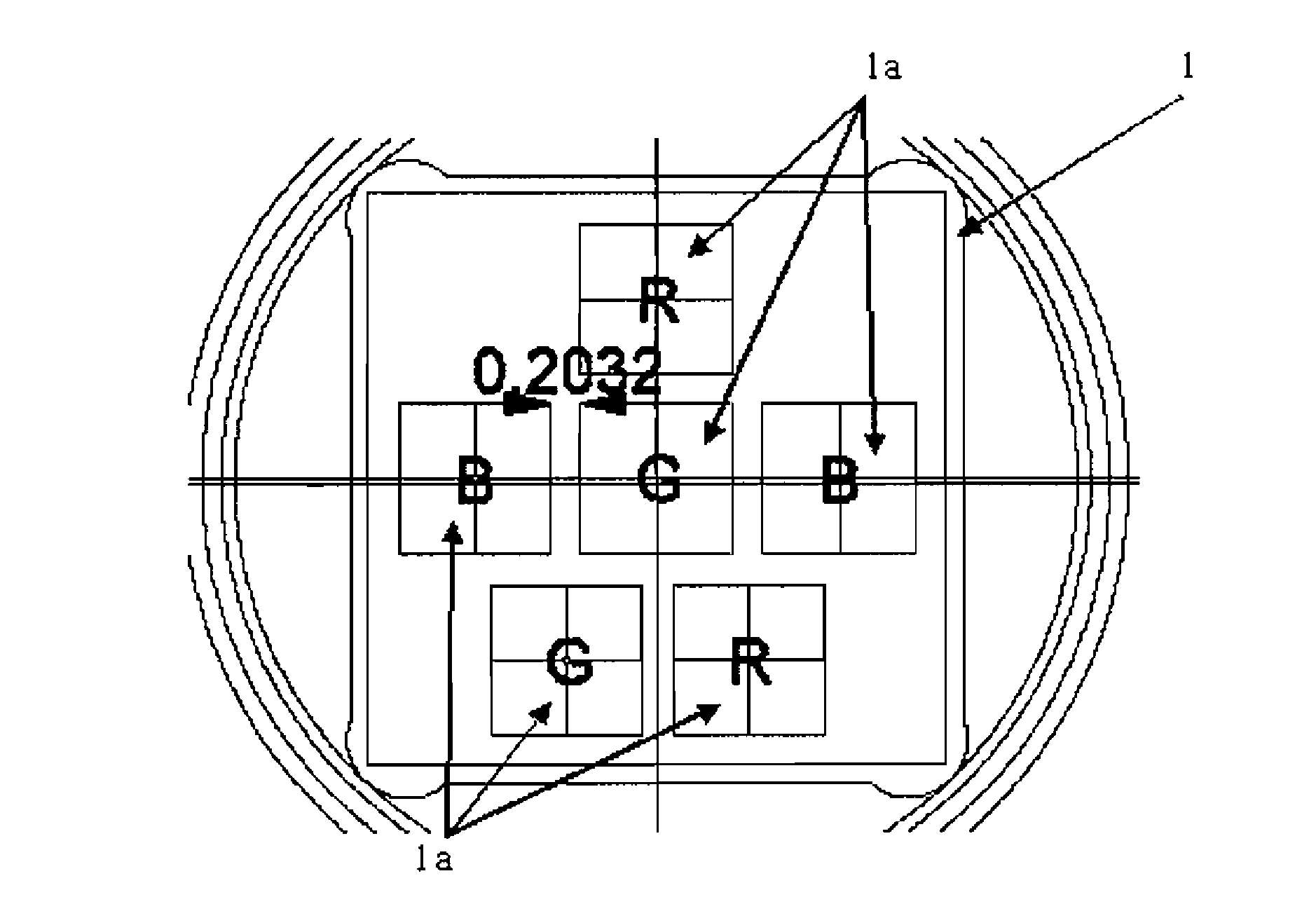
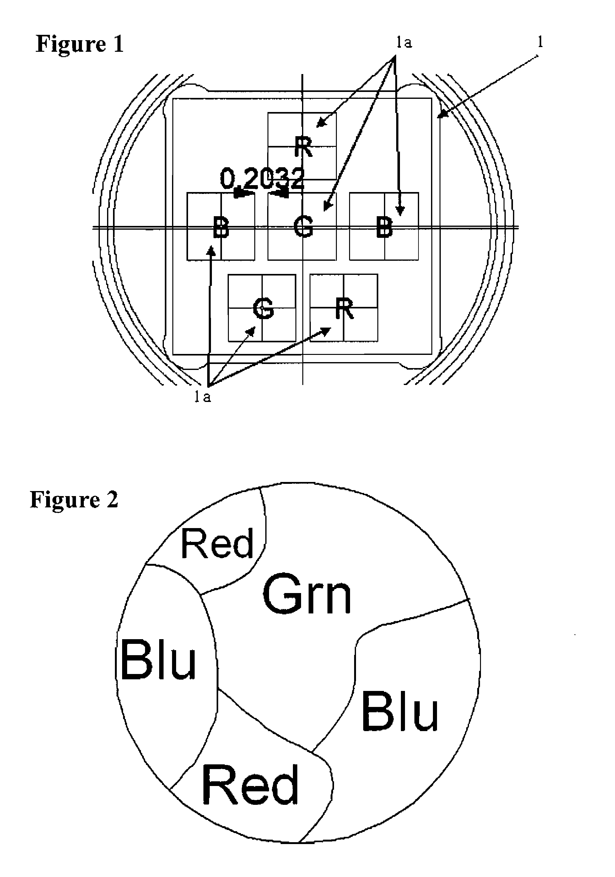
[0045]Traditional LED optics are rotationally symmetric and do not produce a light beam having narrow collimation, nor a light beam having sufficient color uniformity for some applications. The present invention is directed to an optical assembly which performs the dual function of collimation and color homogenization or mixing. The optical assembly disclosed is specifically tailored to match the placement of the solid-state emitters making up the light engine or light producing element. Preferably, the light engine is the 6-LED assembly shown in FIG. 1. The red LEDs are driven with 4.8 volts / 0.35 amperes; green LEDs are driven with 7.4 volts / 0.35 amperes; and blue LEDs are driven with 7.9 volts / 0.35 amperes. The individual LEDs produce a relatively wide lambertian 130° beam angle.

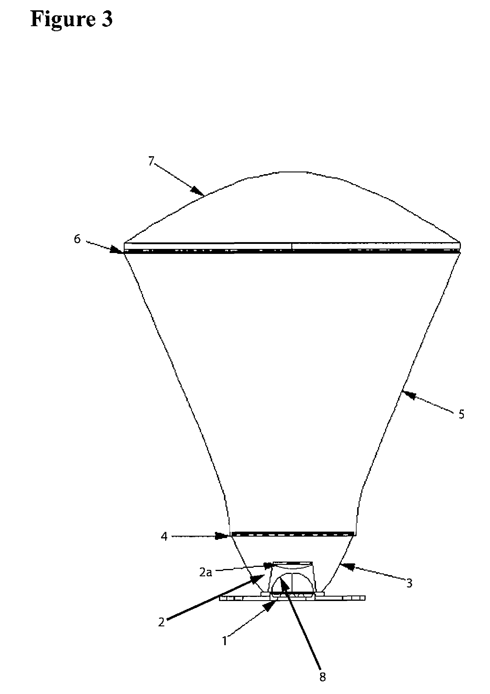
[0046]FIG. 3 shows a first embodiment of the entire assembly, having the following features designed to enhance the collimation and mixing of light, with each of these features discussed in greater detail ...


PUM


Abstract

The present invention relates to an optical assembly which improves color uniformity and improved collimation of light produced by multiple LED light sources in a light engine. The optical assembly is specifically tailored to match the placement of the solid-state emitters making up the light engine or light producing element. Specifically, a shaped free-form spline patch inner collimation lens having an optimized cross-sectional shape and micro-ridges is used to disperse light; multi-lobe TIR collimation lens having an optimized cross-sectional shape and micro-ridges is used to disperse and redistribute phase as well as provide collimation; primary mixing lenslet array having an optimized surface is used to disperse light from the light emitter; a spline profile reflector further mixes and collimates the light; a secondary lenslet array further mixes the light; and a secondary collimation lens further collimates the light.

Description

[0001]This application claims priority from U.S. Provisional Patent Application No. 60 / 871,581, the entire content of which is hereby incorporated by reference in its entirety.[0002]Numerous references including various publications may be cited and discussed in the description of this invention. The citation and / or discussion of such references is provided merely to clarify the description of the present invention and is not an admission that any such reference is “prior art” to the present invention. All references cited and discussed in this specification are incorporated herein by reference in their entirety and to the same extent as if each reference was individually incorporated by reference.FIELD OF THE INVENTION[0003]This invention relates to optical devices. More specifically, the present invention relates to multicolor optical light source assemblies that produce an emitted light collimated to a narrow beam, while achieving acceptable color uniformity.BACKGROUND OF THE INV...

Claims


Application Information

Patent Timeline
IPC IPC(8): F21V9/00F21V7/04F21V7/00
CPCF21V5/002F21V5/04F21Y2101/02F21V7/09F21W2131/406F21V7/0091F21Y2115/10
Inventor BAILEY, EDWARD
Owner LIGHTING SCI GROUP
Learn More