
Child seat presence and/or orientation detection system

a technology for detecting the presence and/or orientation of children, which is applied in the direction of chairs, pedestrian/occupant safety arrangements, vehicular safety arrangements, etc., can solve the problems of airbag deployment that can be dangerous, harmful or even serious danger, and serious injury to children, so as to reduce direct coupling, enhance system sensitivity, and reliably detect the

Inactive Publication Date: 2009-07-02
IEE INT ELECTRONICS & ENG SA
View PDF5 Cites 4 Cited by
  • Summary
  • Abstract
  • Description
  • Claims
  • Application Information

AI Technical Summary

Benefits of technology

[0005]The invention provides a child seat presence and / or orientation detection (CPOD) system with improved detection performance.
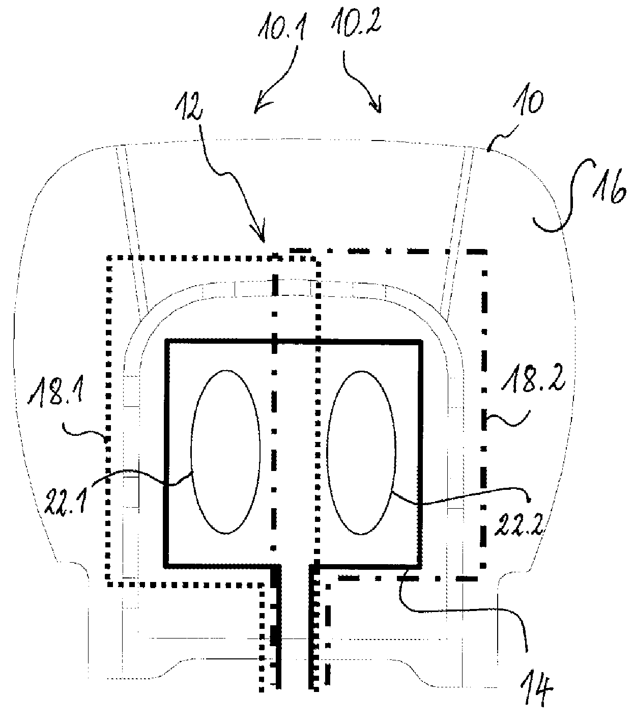
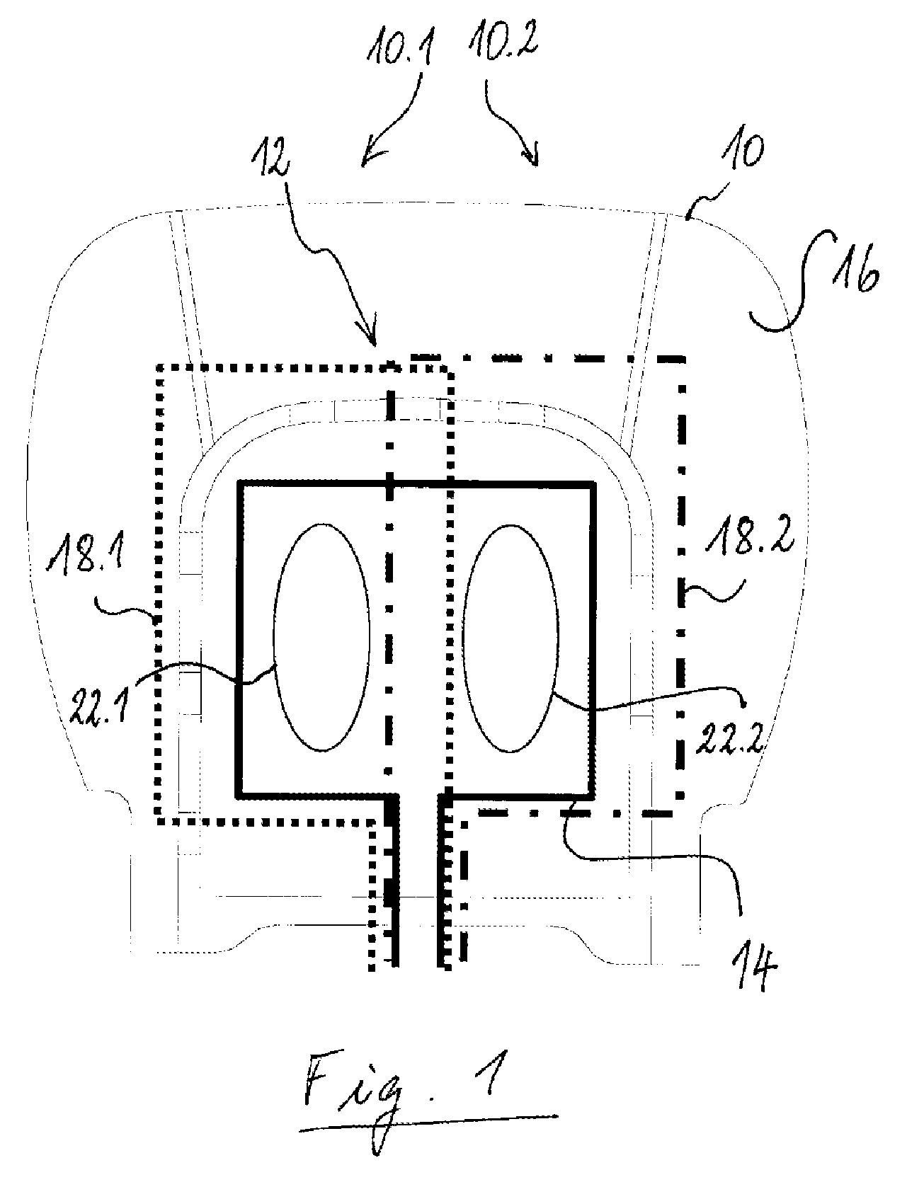
[0007]Preferably, the non-overlap area is dimensioned in such a way that the magnetic flux caused by the loop-shaped transmission antenna in the non-overlap area is substantially equal in magnitude (i.e. in absolute value) to the magnetic flux caused by the loop-shaped transmission antenna in the overlap area. Those skilled in the art will appreciate that in this case, the current induced in the reception antenna by the magnetic flux through the non-overlap area substantially cancels the current induced in the reception antenna by the magnetic flux through the overlap area. Direct electromagnetic coupling between the loop-shaped transmission antenna and the loop-shaped reception antenna is thus significantly reduced and, as a result, the signal-to-noise ratio is strongly enhanced. Preferably, the magnitude of the magnetic flux through the non-overlap area differs from the magnetic flux through the overlap area by less than 35% (with respect to the magnetic flux through the overlap area), more preferably by less than 25% and even more preferably by less than 10%.
[0011]The CPOD system according to the present invention is especially suited for being integrated underneath the crimp channels of a foam cushion, e.g. at a depth of 35 mm or more from the top surface of the seating portion. Although at these depths the metal frame structure of the seat is close to the transmission and the reception antennas, the reduction of direct coupling between the transmission and the reception antennas may enhance the systems sensitivity to such an extend that a child seat and its orientation can be reliably detected.

Problems solved by technology

Although the merit of airbags is nowadays widely recognized in terms of passenger safety, there are, however, situations in which the deployment of an airbag may be harmful, or even constitute serious danger.
For most rear-facing child seats, there is a risk that the deployment of the airbag will throw the child together with the seat violently towards the rear of the vehicle and cause serious injury to the child.
It has also been noted that airbag deployment can also be dangerous for a child installed in a forward-facing child seat, so that some manufacturers recommend that an airbag be disabled whenever the seat with which it is associated is occupied by an auxiliary child seat.
For some types of car seats, however, arranging the antennas close to the upper surface of the seating portion is difficult or even impossible due to the seat design.
In such a case, it may be required to arrange the antennas deeper inside the foam cushion, which however can negatively affect detection performance.

Method used


Image

  • Child seat presence and/or orientation detection system
  • Child seat presence and/or orientation detection system
  • Child seat presence and/or orientation detection system

Examples


Embodiment Construction

[0018]FIG. 1 shows a seating portion 10 of a vehicle seat having a child seat presence and / or orientation detection system 12 incorporated therein. In this embodiment, the CPOD system 12 comprises a loop-shaped transmission antenna 14 arranged centrally underneath the seating surface 16 and two loop-shaped reception antennas 18.1 and 18.2, arranged in the left side 10.1, respectively the right side 10.2 of the seating portion 10.

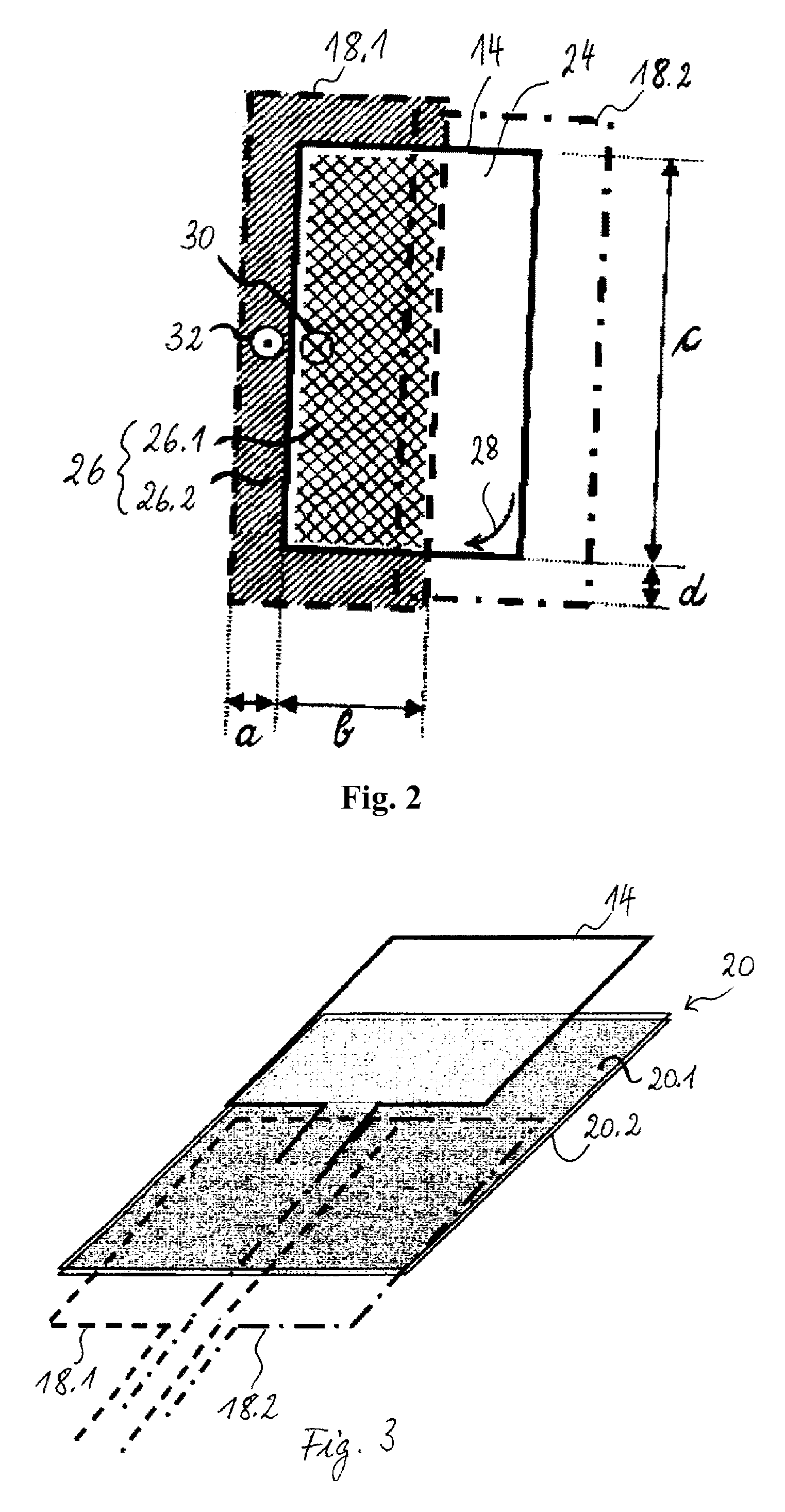
[0019]As illustrated in FIG. 3, the antennas 14, 18.1, 18.2 can be formed on both sides of a thin, flexible substrate 20, the transmitting antenna being arranged on a top side 20.1 of the substrate 20, the reception antennas 18.1, 18.2 being arranged on a bottom side 20.2 of the substrate 20.

[0020]As illustrated in FIGS. 4 and 5, the loop-shaped transmission antenna 14 and the loop-shaped reception antennas 18.1, 18.2 can also be formed on separate substrates 34, 36. In this embodiment, the transmission antenna 14 is printed on a first flexible substrate 34,...


PUM


Abstract

A child seat presence and / or orientation detection system for detecting, on a vehicle seat, presence and / or orientation of a transponder-equipped child seat includes a loop-shaped transmission antenna for transmitting an electromagnetic excitation field and a loop-shaped reception antenna for receiving an electromagnetic response field emitted by a transponder of a child seat in response to the electromagnetic excitation field; the loop-shaped transmission antenna surrounds a first, the loop-shaped reception antenna a second area; the second area includes an overlap area with the first area; the second area also includes a non-overlap area with the first area, i.e. an area which is part of the second area but does not overlap with the first area, such that the magnetic flux caused by the loop-shaped transmission antenna in the non-overlap area is of opposite sign with respect to the magnetic flux caused by the loop-shaped transmission antenna in the overlap area.

Description

TECHNICAL FIELD OF THE INVENTION[0001]The invention generally relates to a system for detecting presence and / or orientation of a child seat placed on a passenger seat of a vehicle, e.g. a motor vehicle equipped with an airbag protection system.BACKGROUND ART[0002]Although the merit of airbags is nowadays widely recognized in terms of passenger safety, there are, however, situations in which the deployment of an airbag may be harmful, or even constitute serious danger. There are currently on the market many types of auxiliary child or infant seats, which are designed to be installed on the front passenger seat. Of these seats, some are designed to face in the direction of travel of the vehicle, and others in the opposite direction with the back turned towards the glove box or the dashboard and some may be installed either way round as desired.[0003]For most rear-facing child seats, there is a risk that the deployment of the airbag will throw the child together with the seat violently...

Claims


Application Information

Patent Timeline
Patent Type & Authority Applications(United States)
IPC IPC(8): B60R21/015B60N2/24H04Q5/22
CPCB60R21/01556
Inventor DECOSTER, YVESORSELLO, ROBERTO
Owner IEE INT ELECTRONICS & ENG SA
Learn More