
Vehicle-mounted device and radio frequency signal amplification method

A technology for radio frequency signals and vehicle-mounted devices, applied in the field of signal detection, can solve problems such as limited system sensitivity, and achieve the effect of compensating for loss and improving system sensitivity

Inactive Publication Date: 2017-06-16
SICHUAN JIUZHOU ELECTRIC GROUP
View PDF6 Cites 0 Cited by
  • Summary
  • Abstract
  • Description
  • Claims
  • Application Information

AI Technical Summary

Problems solved by technology

[0005] Embodiments of the present invention provide a vehicle-mounted device and a method for amplifying radio frequency signals, which are used to solve the technical problem that the improvement of the system sensitivity of the vehicle-mounted device in the prior art is limited, so as to achieve the technical effect of further improving the system sensitivity of the vehicle-mounted device

Method used


Image

  • Vehicle-mounted device and radio frequency signal amplification method
  • Vehicle-mounted device and radio frequency signal amplification method
  • Vehicle-mounted device and radio frequency signal amplification method

Examples


Embodiment 1

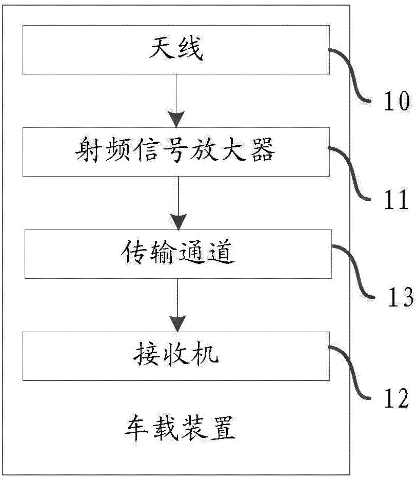
[0052] Please refer to figure 1 , a vehicle-mounted device provided in Embodiment 1 of the application, including:

[0053] Antenna 10;

[0054] A radio frequency signal amplifier 11 is connected to the antenna 10;

[0055] receiver 12;

[0056] A transmission channel 13, connected between the receiver and the radio frequency signal amplifier;

[0057] Wherein, the antenna is used to receive a radio frequency signal; the radio frequency signal amplifier is used to receive the radio frequency signal from the antenna and amplify the radio frequency signal to obtain an amplified radio frequency signal; the receiver passes the radio frequency signal The transmission channel obtains the amplified radio frequency signal from the radio frequency signal amplifier.

[0058] The vehicle-mounted device provided in the embodiment of the present application can be specifically applied to civilian reconnaissance, military reconnaissance, or signal detection in other aspects, which is no...

Embodiment 2

[0092] Based on the same inventive concept, please refer to Figure 4 , the embodiment of the present application also provides a radio frequency signal amplification method, including:

[0093] S401: The antenna in the vehicle-mounted device receives a radio frequency signal;

[0094] S402: The radio frequency signal amplifier in the vehicle-mounted device receives the radio frequency signal from the antenna and amplifies the radio frequency signal to obtain an amplified radio frequency signal;

[0095] S403: The receiver in the vehicle-mounted device obtains the amplified radio frequency signal from the radio frequency signal amplifier through a transmission channel.

[0096] The radio frequency signal method provided by the embodiment of the present application can be applied to a vehicle-mounted device. The vehicle-mounted device can specifically be applied to civilian reconnaissance, military reconnaissance, or signal detection in other aspects. In the embodiment of the ...


PUM


Abstract

The invention discloses a vehicle-mounted device and a radio frequency signal amplification method. The vehicle-mounted device comprises an antenna, a radio frequency signal amplifier, a receiver, and a transmission channel, wherein the radio frequency signal amplifier is connected with the antenna; the transmission channel is connected between the receiver and the radio frequency signal amplifier; the antenna is used for receiving radio frequency signals; the radio frequency signal amplifier is used for receiving the radio frequency signals from the antenna and amplifying the radio frequency signals, and radio frequency signals after amplification are acquired; and the receiver acquires the radio frequency signals after amplification from the radio frequency signal amplifier through the transmission channel. Through the technical scheme provided by the invention, the technical problem that enhancement of the system sensitivity of the vehicle-mounted device in the prior art is limited can be solved.

Description

technical field [0001] The invention relates to the technical field of signal detection, in particular to a vehicle-mounted device and a radio frequency signal amplification method. Background technique [0002] In the field of electronic countermeasure detection, detection distance is a very important performance parameter of detection equipment. A longer detection distance can detect targets earlier to win the corresponding initiative. [0003] In practical applications, for detection equipment that receives signals from specific radiation sources, the detection distance can only be extended by increasing the system sensitivity of the detection equipment. At present, the general methods to improve the sensitivity of the detection equipment system are: to compress the antenna beam width as much as possible to increase the antenna gain; or to use high-performance low-loss cables and low-loss rotary joints to reduce the cable length; or to optimize the receiver scheme and sig...

Claims


Application Information

Patent Timeline
Patent Type & Authority Applications(China)
IPC IPC(8): H04B1/18H03F3/195H03F3/68
CPCH04B1/18H03F3/195H03F3/68H03F2200/294H03F2200/451
Inventor 先登飞
Owner SICHUAN JIUZHOU ELECTRIC GROUP
Learn More