
Electronically controlled pressurized damper

a technology of electric control and damper, which is applied in the direction of vibration dampers, vehicle springs, resilient suspensions, etc., can solve the problems of preparing the valve for the next stroke without taking into account the damping force characteristic of the present stroke, and the risk of cavitation, so as to achieve a simple construction

Active Publication Date: 2009-07-02
OHLINS
View PDF9 Cites 14 Cited by
  • Summary
  • Abstract
  • Description
  • Claims
  • Application Information

AI Technical Summary

Benefits of technology

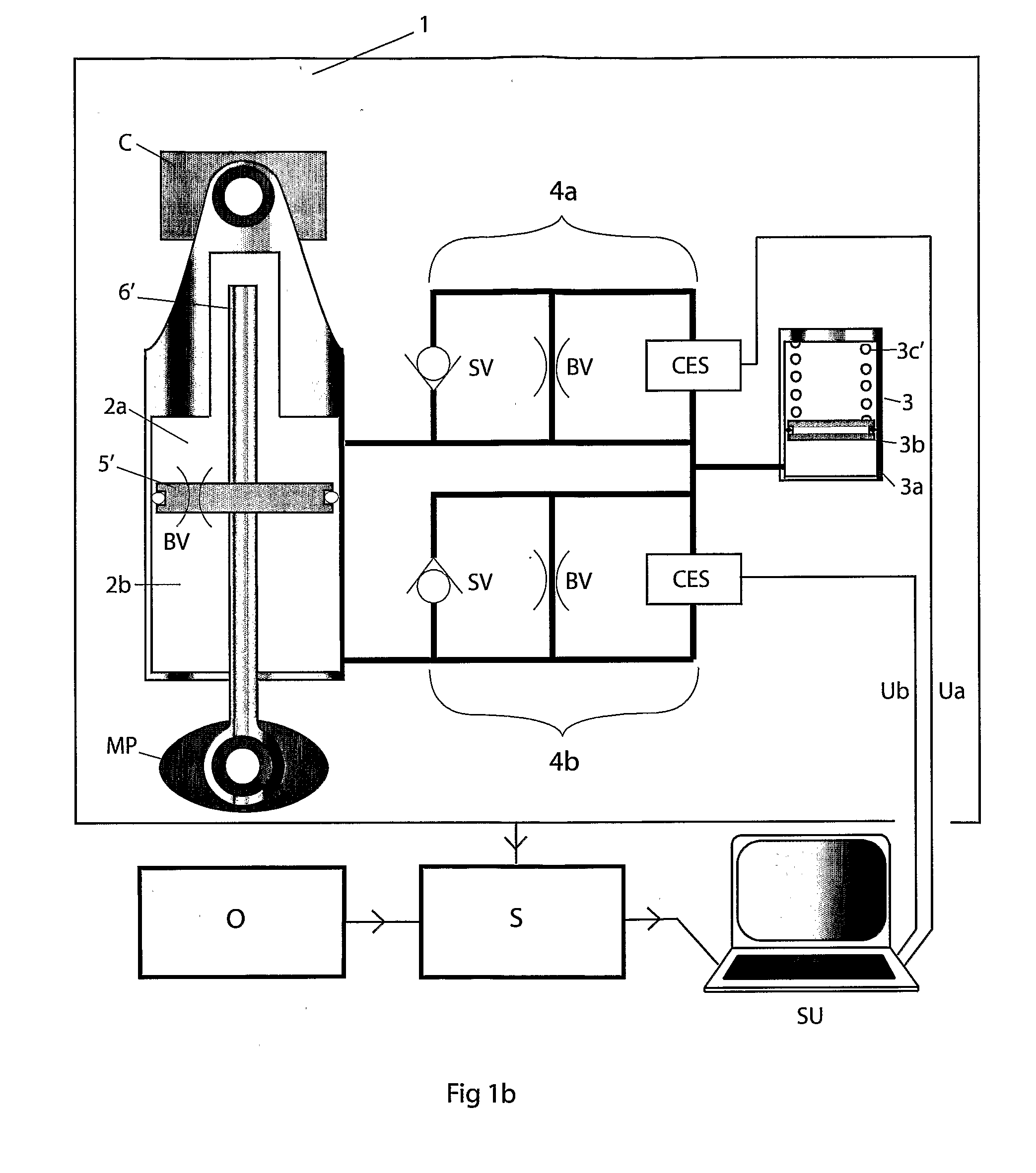
[0013]Since a pressurizing element is always coupled to the low-pressure side of the damper, this ensures that the pressure there never becomes less than zero, so-called positive pressure build-up. The fact that a positive pressure build-up prevails means that cavitation can be prevented and the damping force characteristic in both stroke directions can be adjusted quite separately and independently of one another.
[0016]Since the damping medium flows in the same way through both the compression valve and the return valve, the same type of valve can be used for both stroke directions. This makes the design construction both easier and cheaper to produce. An even simpler construction can be achieved by replacing one of the continuously controlled valves with a discretely controlled valve. This discrete valve may be embodied in a number of different ways, for example by a control unit programmed with a number of predetermined signal values or by a purely mechanical adjustment of the flow aperture through the valve. By placing a leakage flow duct parallel to the valve and connecting arrangement, the low-speed damping can be adjusted separately from the high-speed damping and the electrically adjustable valves can be adjusted to the correct damping characteristic whilst the damper is set up for small strokes and slow movements. A cheaper and simpler valve construction can furthermore be used for the electrically controlled valves.

Problems solved by technology

Yet another problem can arise in rapid continuous adjustment of the damping force characteristic on the basis of output signals delivered by the vehicle sensors.
With previously known dampers this is complicated, since a damper without a positive pressure build-up on the low-pressure side of the piston lacks the capacity to adjust the return and compression damping quite independently of one another.
Preparing a valve for the next stroke without taking account of the damping force characteristic of the present stroke is therefore impossible, it being necessary for the stroke to be completed before the damping force characteristic of the valve can be changed.
Owing to the time lag of the valves, the adjustment also occurs with a time lag which can give rise to an unwanted damping force characteristic and a risk of cavitation, which is particularly manifest in the case of rapid strokes and changes of position.

Method used


Image

  • Electronically controlled pressurized damper
  • Electronically controlled pressurized damper
  • Electronically controlled pressurized damper

Examples


Embodiment Construction

[0025]FIGS. 1a, 1b, 1c and 2 show a schematic diagram of three embodiments of the damper device designed according to claim 1. The parts common to all are described below.

[0026]The damper device 1 is designed to damp the movement between a fixed part C and a moving part MP of a vehicle, for example a car, a motorcycle, a snowmobile or an ATV. The fixed part is, for example, a part of the vehicle chassis whilst the moving part may be a wheel, a ski, a runner or a rotatable handlebar. The different embodiments of the damper will be explained in more detail in conjunction with the separate descriptions of the figures.

[0027]The damper device 1 comprises a part / damper body 2 which is sealed off from the surroundings and the internal volume of which is filled with damping medium and divided into two damper chambers 2a, 2b separated from one another by an element 5 forming a seal against the damper body. The sealing element 5 moves with a stroke predetermined by reciprocal movements of the...


PUM


Abstract

The present invention relates to a device in a vehicle damper which comprises a damping medium-filled damper body (2), in which an element (5, 5′) forming a seal against the damper body divides the damper body into two chambers (2a, 2b). A microprocessor control unit (SU) is coupled to one or more valve and connecting arrangements (4a, 4b, 4c), comprising at least one valve and a number of flow ducts. Respective valves and flow ducts of the valve and connecting arrangement (4a, 4b, 4c) are coupled both to respective damper chambers (2a, 2b) and a pressurizing element (3) common to both of the chambers, so that even in the chamber in which a low pressure prevails there is a positive pressure acting at all times. The valve and connecting arrangements (4a, 4b) comprise a continuously electrically controlled main valve (CES), a non-return valve (SV) and one or more bleed valves (BV, 10a, 10b), the flow through the bleed valve(s) (BV, 10a, 10b) being adjustable separately from the electrically controlled main valve (CES). In the case of small strokes or slow movements the damping medium flows via the bleed valve (BV, 10a, 10b) through one or more separate leakage flow ducts. By locating the leakage flow duct(s) parallel to the valve and connecting arrangement (4a, 4b, 4c) the low-speed damping can be adjusted separately from the high-speed damping. The electrically adjustable main valve (CES) can therefore be adjusted to the correct damping characteristic whilst the damper is set up for small strokes and slow movements.

Description

TECHNICAL FIELD[0001]The present invention relates to a device in a vehicle damper which comprises a damping medium-filled damper body, in which an element forming a seal against the damper body moves with a reciprocating stroke caused by the relative movement between two parts of the vehicle. The element forming a seal against the damper body divides the damper body into two chambers and has a low-pressure side and a high-pressure side owing to the pressure differences in the damping medium under said movement that is induced. One or more valve and connecting arrangements couple the respective damper chambers to a pressurizing element common to both of the chambers, so that even in the chamber in which a low pressure prevails there is a positive pressure acting at all times, so that the damping force characteristic in both stroke directions can be adjusted separately and independently of one another. A continuous electrical signal based on events registered by sensors and adjusted ...

Claims


Application Information

Patent Timeline
IPC IPC(8): B60G17/016F16F9/46
CPCB60G17/0416B60G17/08F16F9/46B60G2202/414B60G2500/114B60G2202/154
Inventor ATSUSHI, ISHII
Owner OHLINS
Learn More