


Quick Research
Generate reliable direction feasibility study reports for your R&D in just a few steps.

Technical Q&A
Discover and master advanced knowledge NOW. Basics, ideas, possibilities, all at once.

Find Solutions
As an expert in R&D theories, this can generate solutions to your technical problems instantly.

Evaluate Feasibility
Analyze your overall solution with one click, know your potential R&D risks in advance.

Monitor Landscape
Get weekly tech updates, stay abreast of the latest tech innovations and key insights.
Petroleum fuel supply method and circuit
a technology of petroleum fuel and supply method, applied in the direction of liquid fuel feeder, machine/engine, mechanical apparatus, etc., can solve the problems of insufficient solution of the problem, no confirmed practical effect of many of these measures, and emission of black smoke containing carbon or h
- Summary
- Abstract
- Description
- Claims
- Application Information
AI Technical Summary
Benefits of technology
Problems solved by technology
Method used
Image

Examples
example 1
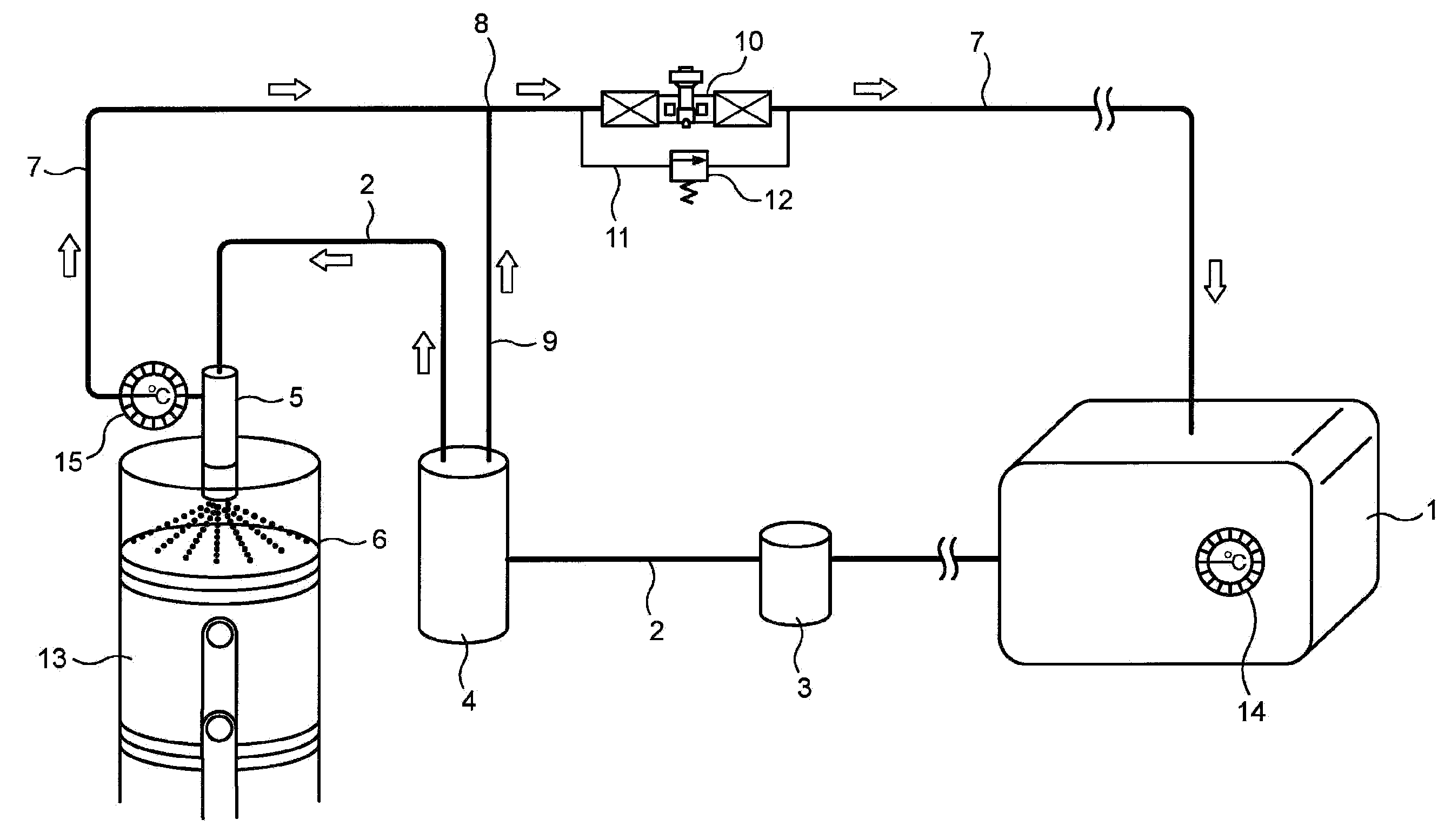
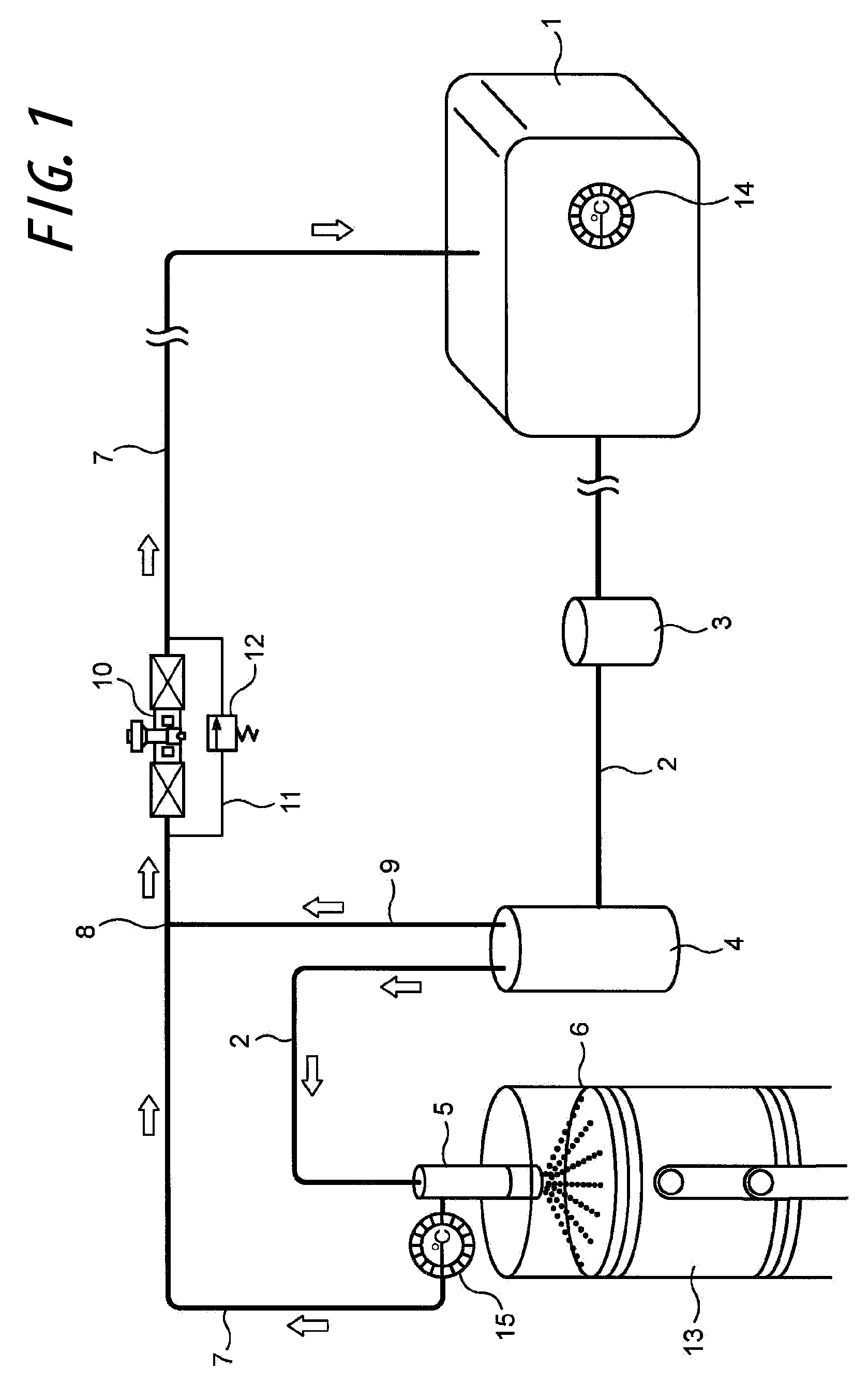
[0058]An automobile mounting a diesel engine having a displacement of 2,500 cc and employing the fuel supply circuit according to the present invention shown in FIG. 1 has been subjected to a test running in a general manner. The travel distance per litter of the fuel was measured, and the fuel consumption was calculated based on the measured data. With reference to the data of a comparative experiment wherein the fuel temperature was 30° C. and the fuel consumption was 7 km / litter, when the flow-rate regulating valve 10 in FIG. 1 was closed at a closure degree of 50%, the fuel temperature was raised to 50° C. and the fuel consumption was 9 km / litter, which means that the fuel consumption was improved by 29% with reference to the control data. Furthermore, when the flow-rate regulating valve 10 in FIG. 1 was closed at a closure degree of 100%, the fuel temperature was raised to 67° C. and the fuel consumption was 11 km / litter, which means that the fuel consumption was improved by 57...
example 2
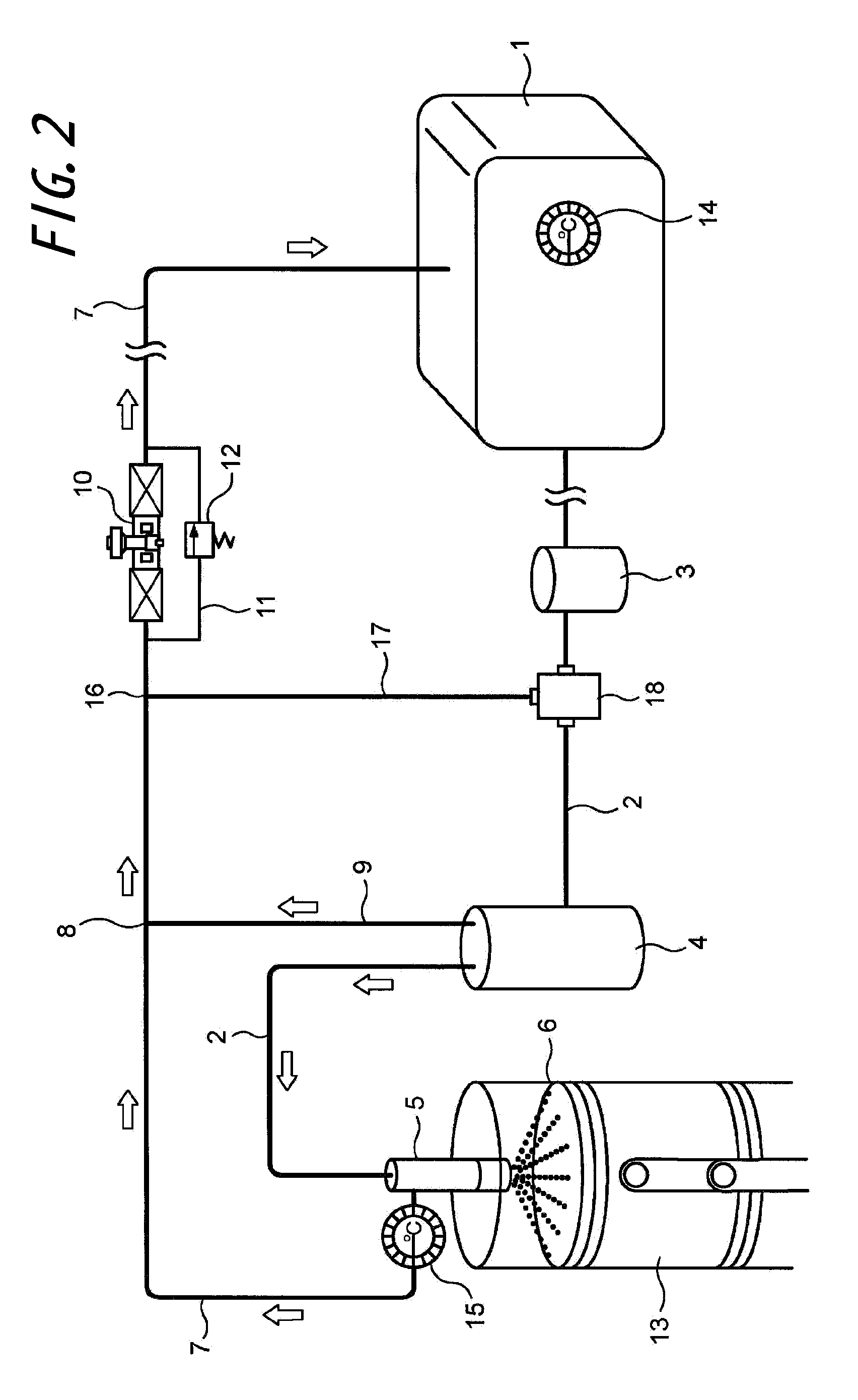
[0059]An automobile mounting a diesel engine having a displacement of 2,500 cc and employing the fuel supply circuit of the present invention shown in FIG. 2 has been subjected to a test running. The travel distance per litter of the fuel was measured, and the fuel consumption was calculated based on the measured data. With reference to the data of the comparative experiment wherein the fuel temperature was 30° C. and the fuel consumption was 7 km / litter, when half of the return fuel was fed into the sub-tank 18 and the mixed fuel with the fuel from the fuel tank 1 was thus supplied to the fuel injection nozzle 5 with the flow-rate regulating valve in FIG. 2 closed at a closure degree of 50%, the fuel temperature was raised to 60° C. and the fuel consumption was 10 km / litter, which means that the fuel consumption was improved by 42% with reference to the control data. Furthermore, when all of the return fuel was fed into the sub- tank 18 and the mixed fuel with the fuel from the fue...
PUM
 Abstract
Description
Claims
Application Information
 - R&D Engineer
- R&D Manager
- IP Professional
- Industry Leading Data Capabilities
- Powerful AI technology
- Patent DNA Extraction
Browse by: Latest US Patents, China's latest patents, Technical Efficacy Thesaurus, Application Domain, Technology Topic, Popular Technical Reports.
© 2024 PatSnap. All rights reserved.Legal|Privacy policy|Modern Slavery Act Transparency Statement|Sitemap|About US| Contact US: help@patsnap.com