
Identification managment system for electronic device authentication

a technology of identification management system and electronic device, which is applied in the field of identification management system for electronic device authentication, can solve the problems of user inconvenience and inability to receive the service received by another user in another service providing system

Inactive Publication Date: 2009-06-25
PANASONIC CORP
View PDF6 Cites 63 Cited by
  • Summary
  • Abstract
  • Description
  • Claims
  • Application Information

AI Technical Summary

Benefits of technology

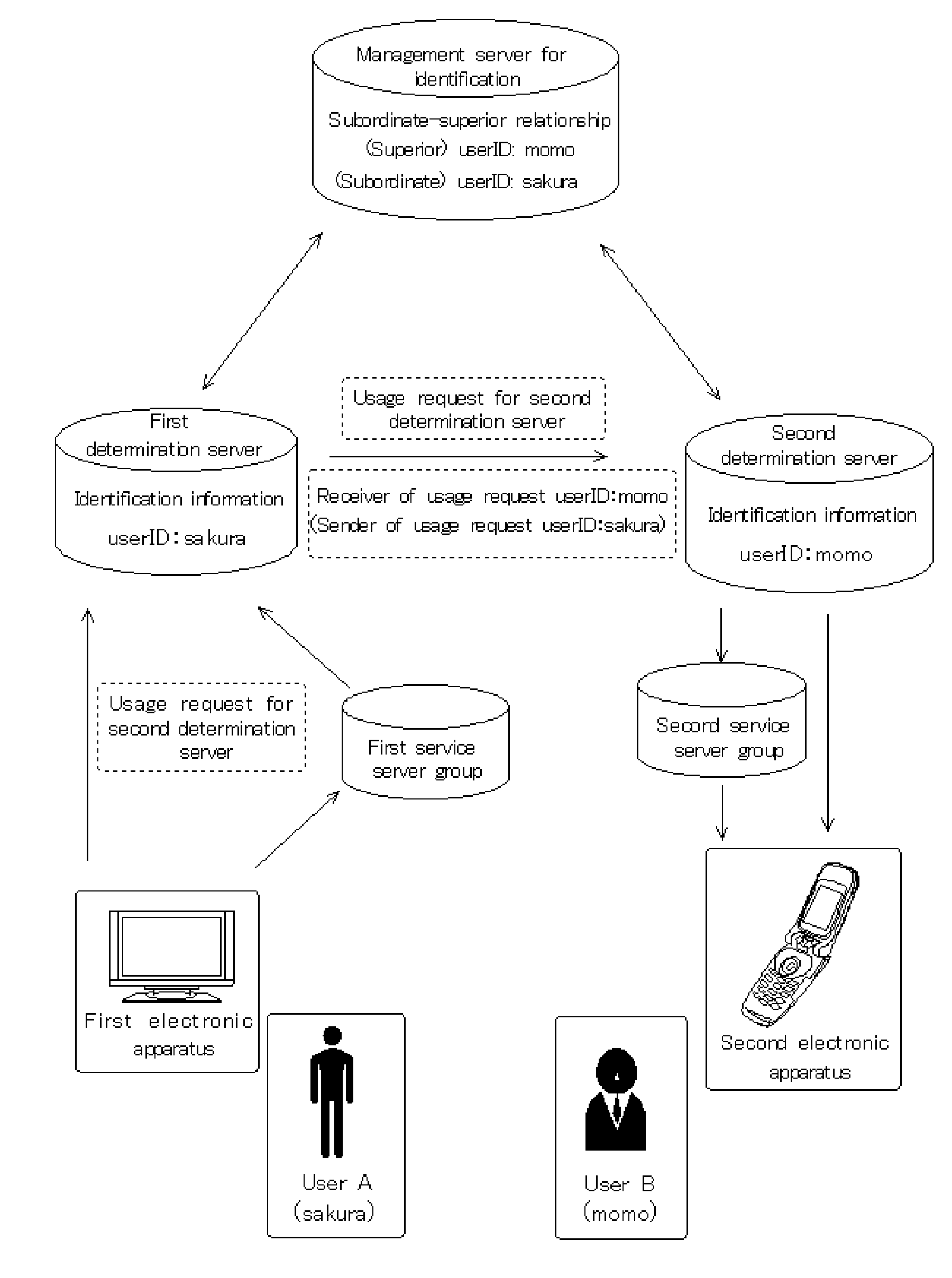
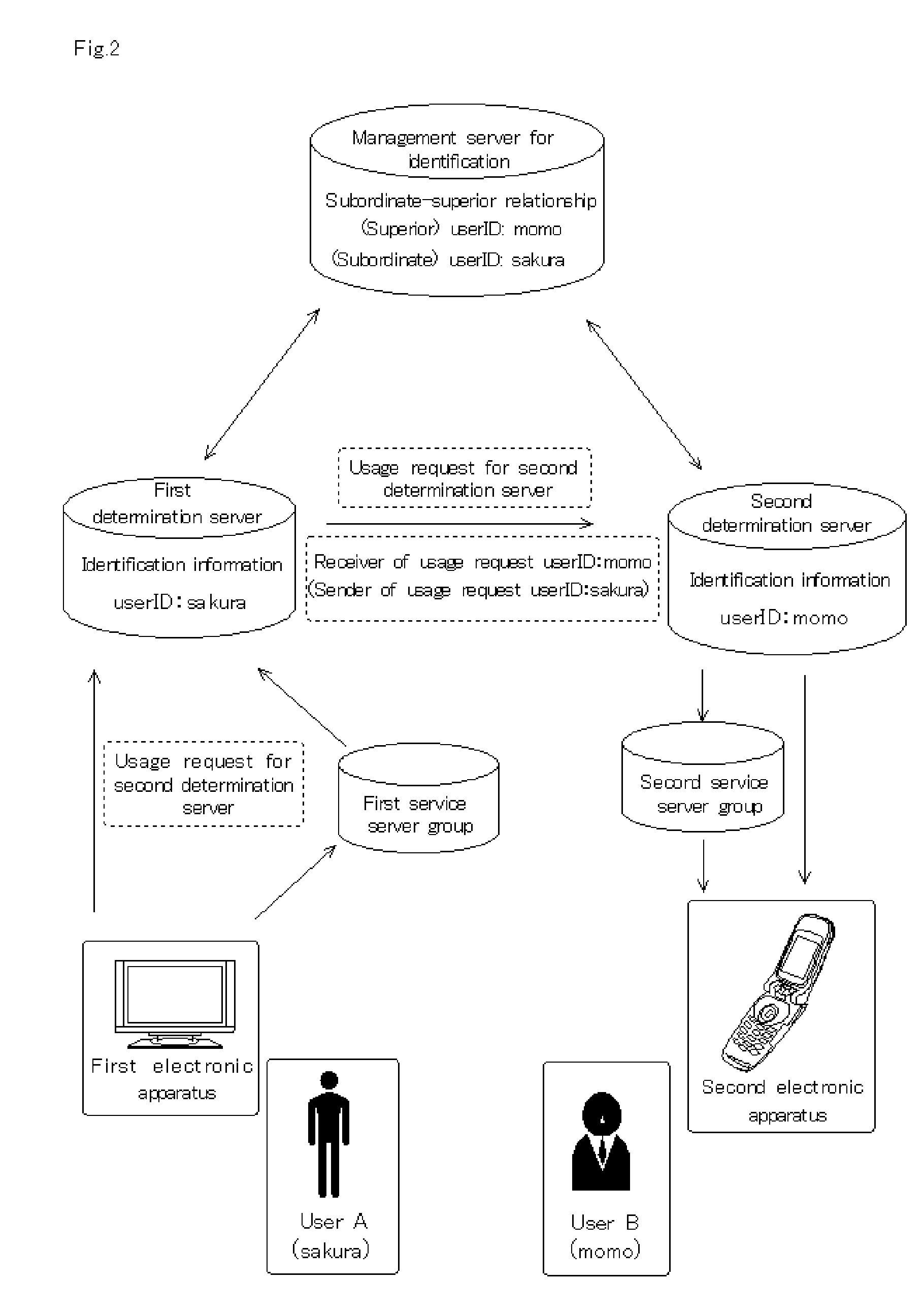
[0014]According to the present invention, it becomes possible to identify subordinate-superior relationship between users and uniqueness of each user over a plurality of service systems. Therefore, it becomes unnecessary that one electronic apparatus is bound by one service system, thereby removing boundaries between service systems. Accordingly, it is possible to use a plurality of service systems across boundaries by using only one electronic apparatus.DETAILED DESCRIPTION OF THE PREFERRED EMBODIMENTS
[0182]In the above disclosed system configuration, one electronic apparatus is not bound by one service system, thereby removing boundaries between service systems. Moreover, in the system, the first user can receive the service received by designating the user, who is proved to have the subordinate-superior relationship, as the second user, thereby improving user-friendliness.

Problems solved by technology

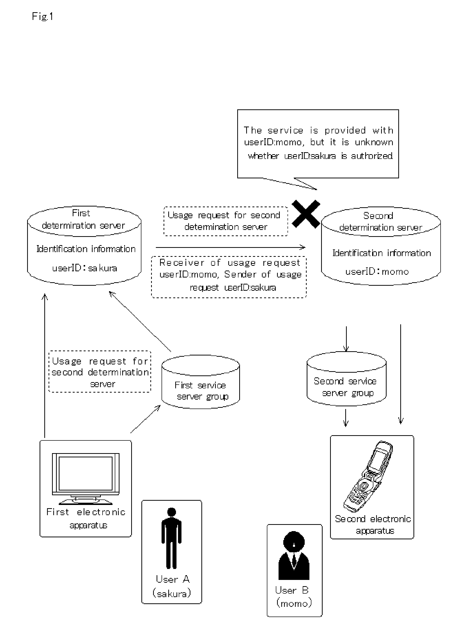
However, in the conventional vertically-integrated system, since authentication for the settlement of payment for service provision is carried out only with respect to each apparatus receiving the service, for example, in cases where a user desires to pay by another user's terminal apparatus through a credit card company or a bank account, the above system cannot be utilized, thereby causing inconveniences for the user.
In addition, there is a deficiency that a user cannot receive the service received by another user in another service providing system.

Method used


Image

  • Identification managment system for electronic device authentication
  • Identification managment system for electronic device authentication
  • Identification managment system for electronic device authentication

Examples


first embodiment

Configuration for Implementing First Embodiment

[0077]FIG. 20 is a diagram showing an example of configuration for implementing the first embodiment. In FIG. 20, the first determination server (2030) is explained. As shown in FIG. 21, a physical configuration of the first determination server (2030) is implemented by the hardware (2031) configured by a CPU, a memory, a hard disk, an input / output device, a network interface (I / O) etc. Logically speaking, an operating system (2032), basic software for abstraction of functions of the hardware (2031), or for managing operation of the hardware (2031) is operated, and program configured by including modules such as a first storage module for correlation (2033), an output module for first proof request (2034), a receiving module for first proof’ (2035), and an output module for service request with proof (2036), which are for implementing the first storage unit for correlation (511), the output unit for first proof request (512), the receiv...

second embodiment

Configuration for Implementing Second Embodiment

[0113]FIG. 33 is a diagram showing an example of configuration for implementing the second embodiment. In FIG. 33, the management server for identification (3350) is explained. As shown in FIG. 33, a physical configuration of the management server for identification (3350) is implemented by the hardware (3350) configured by a CPU, a memory, a hard disk, an input / output device, a network interface (I / O) etc. Logically speaking, an operating system (3352), basic software for abstraction of functions of the hardware (3351), or for managing operation of the hardware (3351) is operated, and program configured by including modules such as a management module for identification (3353), a receiving module for service request with proof request (3354), a search module for management unit for identification (3355), and an output module for second service request with proof (3356), which are for implementing the management unit for identification...

third embodiment

Configuration for Implementing Third Embodiment

[0144]FIG. 44 is a diagram showing an example of configuration for implementing the third embodiment. In FIG. 44, the second determination server (4440) is explained. As shown in FIG. 44, a physical configuration of the second determination server (4440) is implemented by the hardware (4440) configured by a CPU, a memory, a hard disk, an input / output device, a network interface etc. Logically speaking, an operating system (4442), basic software for abstraction of functions of the hardware (4441), or for managing operation of the hardware (4441) is operated, and program configured by including modules such as the second storage module for correlation (4443), the receiving module for service request (4444), the output module for second proof request (4445), the receiving module for second proof (4446), and the second search module (4447), which are for implementing the second storage unit for correlation (3521), the receiving unit for ser...


PUM


Abstract

The conventional vertical integration system management form has a problem that a first user cannot receive a service provided by a second user belonging to another service system. To cope with this, a following system is suggested. That is, according to a second judgment server use request from a first electronic device used by a first user, an identification management server which has received a guarantee request outputted from a first judgment server searches for master-slave relationship information based on a common identifier. According to the search result, a guarantee is outputted. According to the guarantee, the first judgment server outputs a guaranteed service request to the second judgment server. Thus, the first user can receive the service used by the second user belonging to other vertical integration type system.

Description

BACKGROUND OF THE INVENTION[0001]1. Field of the Invention[0002]The present invention relates to an identification management system for authentication of electronic devices.[0003]2. Description of the Related Art[0004]In Japanese Unexamined Patent Application Publication No. 2004-227055, a service providing system provides service requested from an electronic device, and processes settlement for the provided service. In such service providing system, a so-called vertically-integrated management form is normally used. Therefore, a manager of the service providing form manages a determination server for authenticating an electronic apparatus, and service provider who provides the service with the electronic apparatus makes a contract with the manager of the service providing system, and provides the service only with the electronic apparatus authenticated by the determination server. According to such a management form, it is possible to provide the service only with the electronic a...

Claims


Application Information

Patent Timeline
IPC IPC(8): H04L9/32G06F21/00G06F17/30G06F21/31G06Q30/04G06Q30/06G06Q50/00G06Q50/10
CPCH04L63/0815
Inventor TOJO, MASAAKIFUKUI, KOHTAROTOMITA, KOJI
Owner PANASONIC CORP
Learn More