
Methods and Apparatus for Fault Identification in Border Gateway Protocol Networks

a technology of border gateway protocol and fault identification, applied in data switching networks, frequency-division multiplexes, instruments, etc., can solve problems such as bgp network problems and bgp network problems

Inactive Publication Date: 2009-06-25
LYFT INC
View PDF5 Cites 37 Cited by
  • Summary
  • Abstract
  • Description
  • Claims
  • Application Information

AI Technical Summary

Benefits of technology

[0005]Among its several aspects, the present invention recognizes the need for automated systems and techniques for diagnosing a communication failure experienced by a customer, with the diagnosis including determining whether the failure results from a failure of physical connections or data transport elements, or a routing failure by t

Problems solved by technology

The analysis may include examination of provider network routing information to determine whether proper BGP routing information appears for each customer channel served by the portions of the provider network under examination, with failure indicating a BGP network problem.
If proper routing information does not appear, a BGP network problem is noted.

Method used


Image

  • Methods and Apparatus for Fault Identification in Border Gateway Protocol Networks
  • Methods and Apparatus for Fault Identification in Border Gateway Protocol Networks
  • Methods and Apparatus for Fault Identification in Border Gateway Protocol Networks

Examples


Embodiment Construction

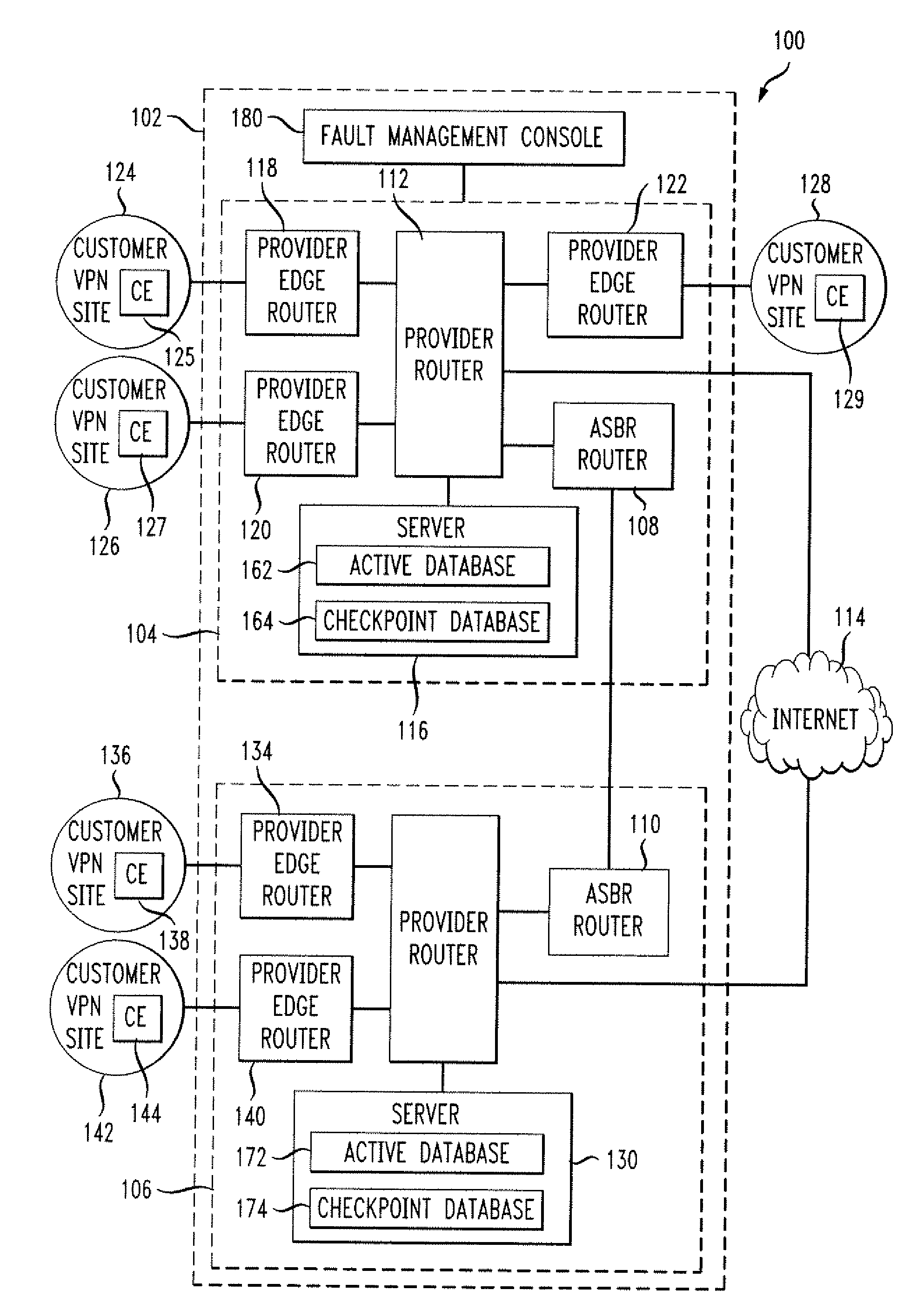
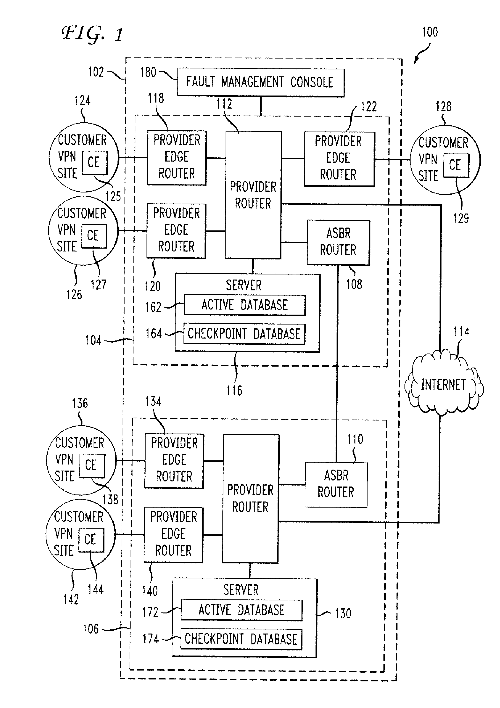
[0011]FIG. 1 illustrates a communication system 100, according to an aspect of the present invention. The system 100 includes a multi-protocol label switching (MPLS) network 102, providing services to numerous customer systems, of which a few representative systems are illustrated here. The MPLS network 102 illustrated here includes a domestic network 104 and a most of world (MOW) network 106, communicating with one another through asynchronous boundary routers 108 and 110. The network 104 includes a provider router 112 serving as a backbone, providing communications to client devices and networks and providing connections to services and additional networks, such as the Internet 114. The network 104 employs a server 116, providing administrative and other services needed for network management.

[0012]To provide connectivity to various customer networks and devices, the network 104 employs a plurality of routers, referred to here as provider edge routers. The network 104 includes pro...


PUM


Abstract

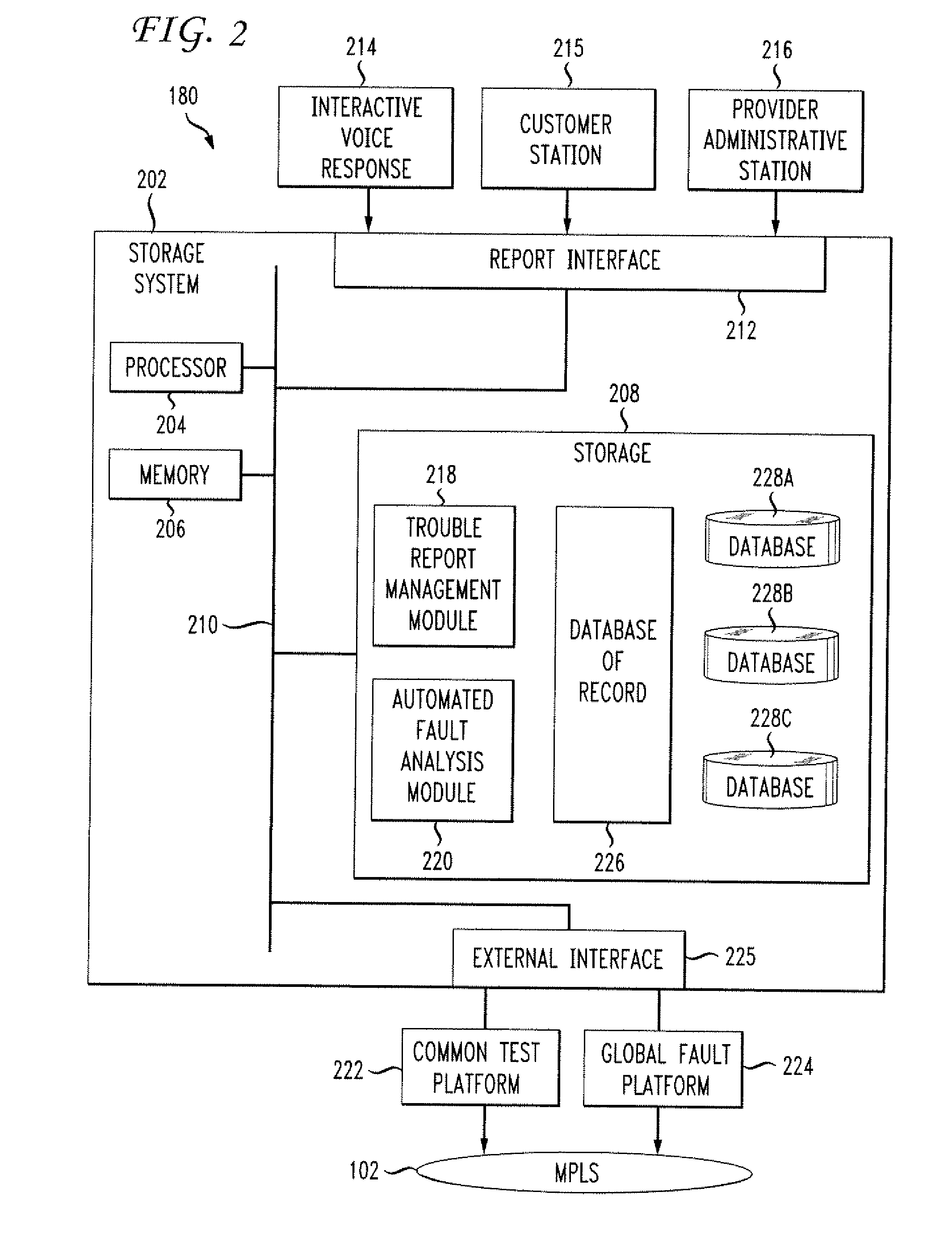
Systems and techniques for fault analysis in a data communication system. A fault analysis console in a provider network serving one or more customer networks responds to a reported loss of connectivity in the customer network by analyzing traffic statistics for a router serving the customer network. If traffic statistics indicate network functionality, border gateway protocol status is evaluated for logical channels being served by the router. Test communications are performed for customer edge router addresses for the logical channels and border gateway protocol status is evaluated for each customer edge router address. Test communications are then performed from a local provider edge router to each remote customer edge router being served.

Description

FIELD OF THE INVENTION[0001]The present invention relates generally to improvements to data communication. More particularly, the invention relates to improved systems and techniques for examining communication failures in systems employing border gateway protocol (BGP), identifying whether the communication failure is due to a problem with the network layer in the communication protocol rather than the physical or data transport layers, and isolating the source of the failure.BACKGROUND OF THE INVENTION[0002]Modern large communication systems provide for transmission of data over packet switched networks. Communication is frequently conducted according to the open systems interconnection basic reference (OSI) model, in which communication is thought of as a hierarchy of layers, from layer 7, the application layer, to layer 1, the physical layer. The application layer defines interfaces and services are provided to end user applications in order to organize data for communication, a...

Claims


Application Information

Patent Timeline
IPC IPC(8): G06F11/00
CPCH04L12/2697H04L41/0631H04L41/0677H04L69/40H04L43/0876H04L43/50H04L45/00H04L43/0811
Inventor QIAN, ZHIQIANGBAJPAY, PARITOSHDARDASHTI, MOJGANZINNIKAS, MICHAEL J.
Owner LYFT INC
Learn More