
Industrial arc fault circuit interrupter and method of detecting arcing conditions

a fault circuit interrupter and industrial arc technology, applied in the field of circuit interrupters, can solve the problems of arc flash, circuit breakers may trip too slowly, and conventional arc fault circuit interrupters (afcis) may trip too quickly

Active Publication Date: 2009-06-25
EATON INTELLIGENT POWER LIMITED
View PDF5 Cites 65 Cited by
  • Summary
  • Abstract
  • Description
  • Claims
  • Application Information

AI Technical Summary

Benefits of technology

[0015]In accordance with one aspect of the invention, a circuit interrupter comprises: a number of poles, each of the number of poles comprising a pair of separable contacts; an operating mechanism structured to open and close the pair of separable contacts for the number of poles; and a trip mechanism cooperating with the operating mechanism to trip open the number of poles, the trip mechanism comprising a processor and further comprising for each of the number of poles: a first current sensor structured to sense current flowing through the pair of separable contacts of a corresponding one of the number of poles, a number of second current sensors structured to sense a number of high frequency current signals from the current flowing through the pair of separable contacts of the corresponding one of the number of poles, a number of bandpass filters, each of the number of bandpass filters including an input receiving one of the number of high frequency current signals and an output, a number of peak detectors, each of the number of peak detectors including an input receiving the output of a corresponding one of the number of bandpass filters and an output, and a number of envelope detectors, each of the number of envelope detectors including an input receiving the output of a corresponding one of the number of bandpass filters and an output, wherein the processor is structured to: count a count of occurrences of the output of each of the number of envelope detectors exceeding a first predetermined value, maintain a number of temporary values corresponding to the output of each of the number of peak detectors, determine an arc fault trip time as a function of the sensed current flowing through the pair of separable contacts for the number of poles, determine if the output of any of the number of peak detectors is greater than a second predetermined value, and, if so, responsively increase a corresponding one of the number of temporary values by a third predetermined value and, if not, decrease the corresponding one of the number of temporary values by a fourth predetermined value, determine if a predetermined function of the number of temporary values is greater than a fifth predetermined value, and, if so, for each of the number of peak detectors, add the corresponding one of the number of temporary values to an accumulator, and if not, decrease the accumulator by a sixth predetermined value, and cause the operating mechanism to trip open the number of poles if: (a) a difference between the count corresponding to the current one of the half cycles having a polarity and the count corresponding to the immediately previous one of the half cycles having the same polarity is at least two, (b) the accumulator is greater than a seventh predetermined value, and (c) the arc fault trip time is reached.

Problems solved by technology

These circuit breakers can also have a ground fault trip function that typically also incorporates a delay time.
The potential for arc flash resulting from an accidental fault requires that such personnel wear protective clothing.
The ARMS reduces arc flash energy by lowering the trip level of a fault and is limited to fault levels higher than the frame rating of a molded case circuit breaker.
However, such circuit breakers may trip too slowly due to the breaker withstand requirement in some cases.
In industrial applications, conventional arc fault circuit interrupters (AFCIs) may trip too quickly for “arcing” arising during conventional circuit breaker switching, which may last up to about a full cycle or so.

Method used


Image

  • Industrial arc fault circuit interrupter and method of detecting arcing conditions
  • Industrial arc fault circuit interrupter and method of detecting arcing conditions
  • Industrial arc fault circuit interrupter and method of detecting arcing conditions

Examples


example 1

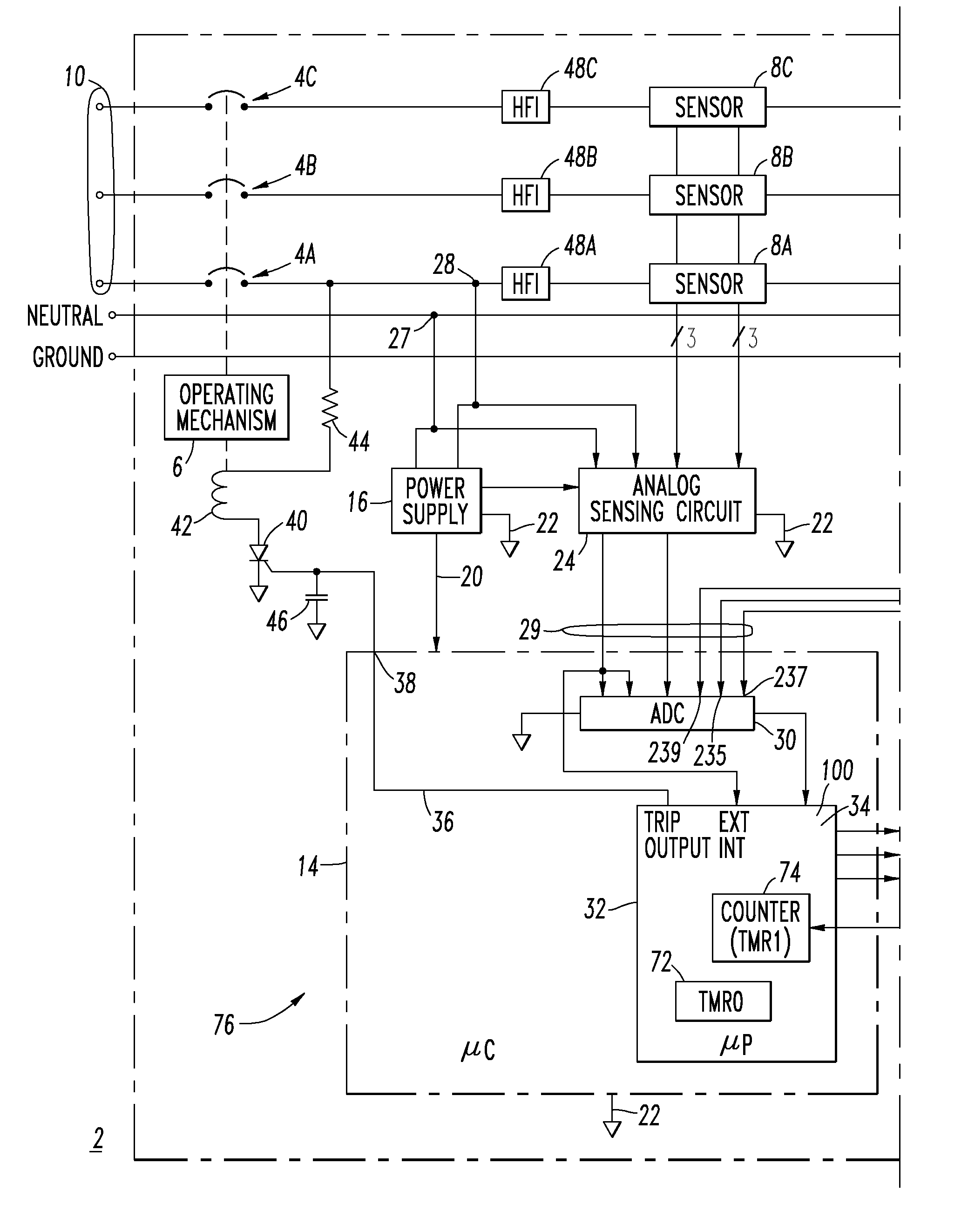
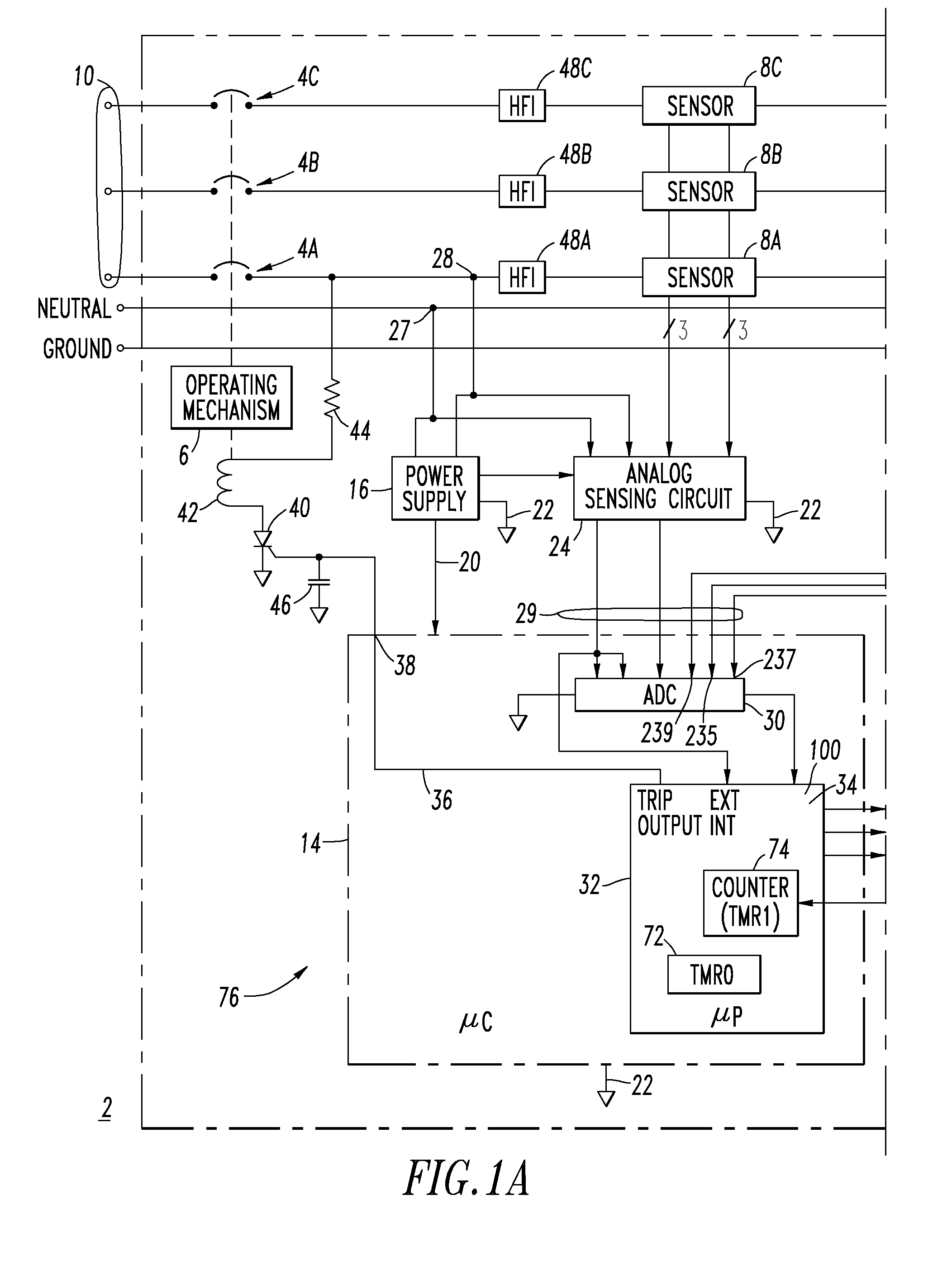
[0054]The disclosed circuit interrupter 2 may be, for example and without limitation, a molded case circuit breaker (MCCB) for industrial applications.

example 2

[0055]For a single-phase system, instead of checking for a three-phase current imbalance for a three-phase system (at 104 of FIG. 2), there is the conventional check if the difference between the load current and the load-neutral current is significantly different than zero (e.g., without limitation, any suitable equipment protection ground fault trip level; about 30 mA or higher).

example 3

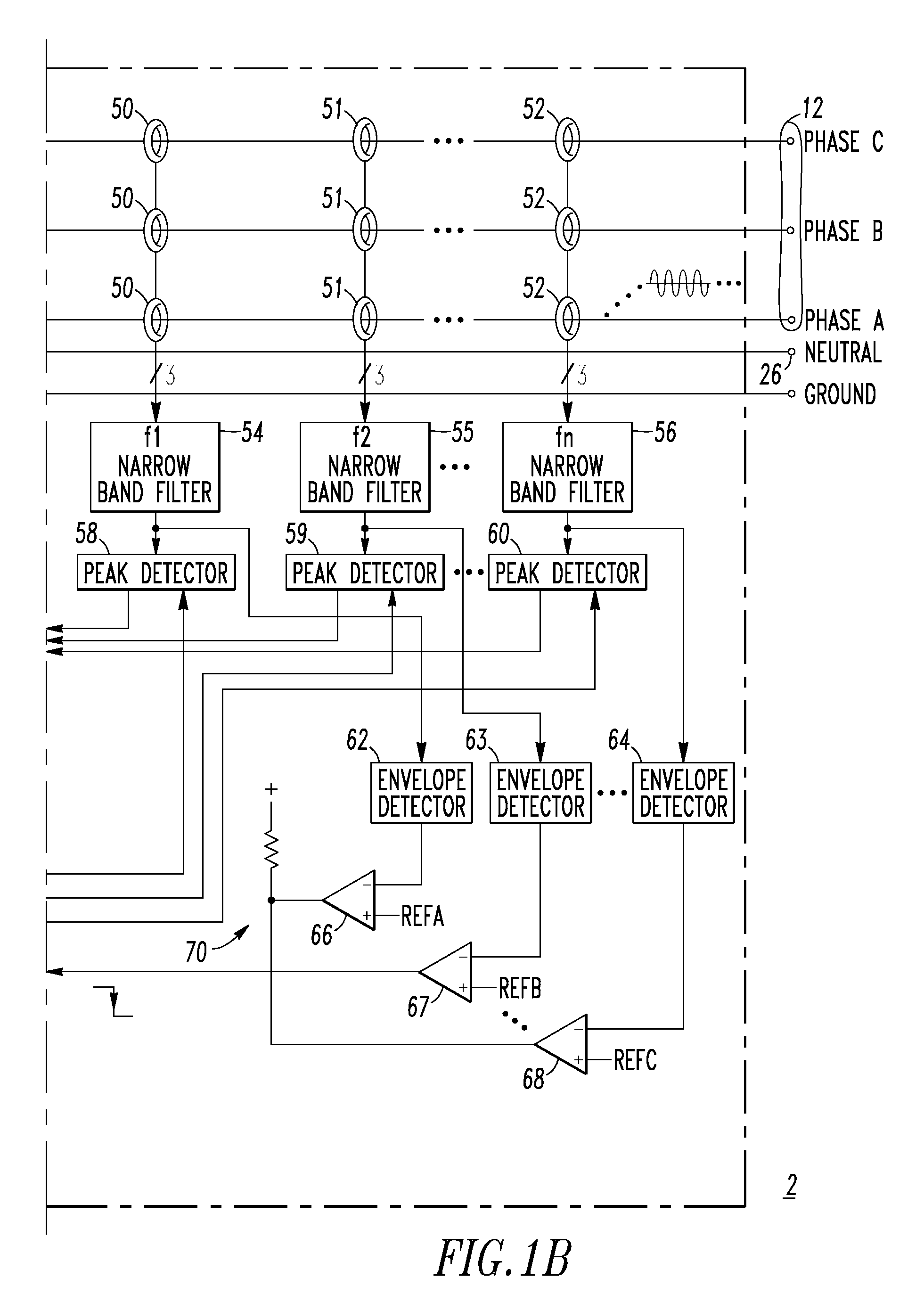
[0056]For each of the number of high frequency current signals, there is one narrow band filter (54, 55 or 56), one peak detector (58, 59 or 60), one envelope detector (62, 63 or 64) and one corresponding comparator (66, 67 or 68). Since there may be one or more high frequency current signals, there may be any number of sets of the narrow band filters, the peak detectors, the envelope detectors and the corresponding comparators.


PUM


Abstract

A method of detecting arcing conditions includes sensing current and HF signals therefrom; bandpass filtering the HF signals and providing filtered signals; detecting peak signals and envelopes from the filtered signals; counting occurrences of the envelopes exceeding a first value; maintaining temporary values corresponding to the peak signals; determining a trip time as a function of the current; determining if any peak signal is greater than a second value, and responsively increasing a temporary value and, otherwise, decreasing the temporary value; determining if a predetermined function of the temporary values is greater than a fifth value, and adding the temporary values to an accumulator, and otherwise, decreasing the accumulator; and tripping open the power circuit if: a difference between the occurrences of current and immediately previous half cycle having the same polarity is at least two, the accumulator is greater than a seventh value, and the trip time is reached.

Description

BACKGROUND OF THE INVENTION[0001]1. Field of the Invention[0002]This invention pertains generally to circuit interrupters and, more particularly, to arc fault circuit interrupters. The invention also relates to methods of detecting arcing conditions.[0003]2. Background Information[0004]Maintenance personnel often need to work on low voltage electric power circuits that are energized, for instance, when testing circuit breakers. The circuit breakers have trip functions designed to protect the power circuits from overloads and overcurrents. These trip functions typically include a delayed trip function that allows downstream circuit breakers closer to the fault to respond first in order to limit interruption of service in that circuit only. The delayed trip function also permits temporary overloads, such as those associated with the starting current of relatively large motors.[0005]The coordination between circuit breakers can be enhanced by zone interlocking in which a breaker lower ...

Claims


Application Information

Patent Timeline
IPC IPC(8): H02H3/16
CPCH02H9/00H02H1/0015
Inventor BEATTY, JR., WILLIAM E.CAROLAN, DOUGLAS J.ZHOU, XIN
Owner EATON INTELLIGENT POWER LIMITED
Learn More