
Position-measuring device and method for determining absolute position

Active Publication Date: 2009-06-25
DR JOHANNES HEIDENHAIN GMBH
View PDF15 Cites 7 Cited by
  • Summary
  • Abstract
  • Description
  • Claims
  • Application Information

AI Technical Summary

Benefits of technology

[0008]Example embodiments of the present invention provide a position-measuring device having improved dependability and / or operational reliability. Example embodiments of the present invention provide a method for determining absolute position that exhibits improved dependability and / or operational reliability

Problems solved by technology

When working with such an optical scanning principle, it is especially problematic that the reliability of the reading of the code track is dependent on the precision of the imaging of the part of the code track relevant for the reading, onto the detector array.
Because of this, undefined states may occur and false position values may even be ascertained.

Method used


Image

  • Position-measuring device and method for determining absolute position
  • Position-measuring device and method for determining absolute position
  • Position-measuring device and method for determining absolute position

Examples


Embodiment Construction

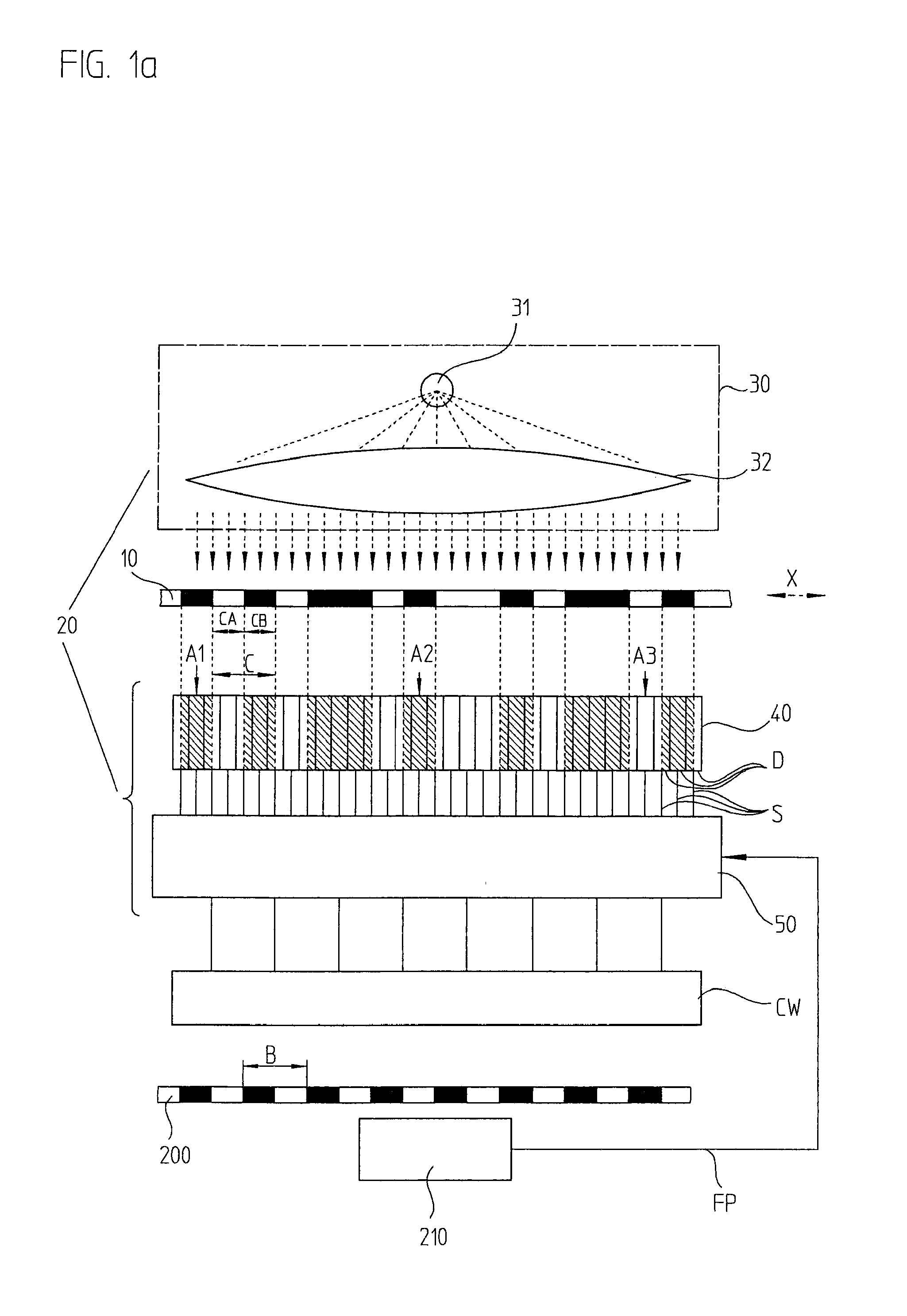
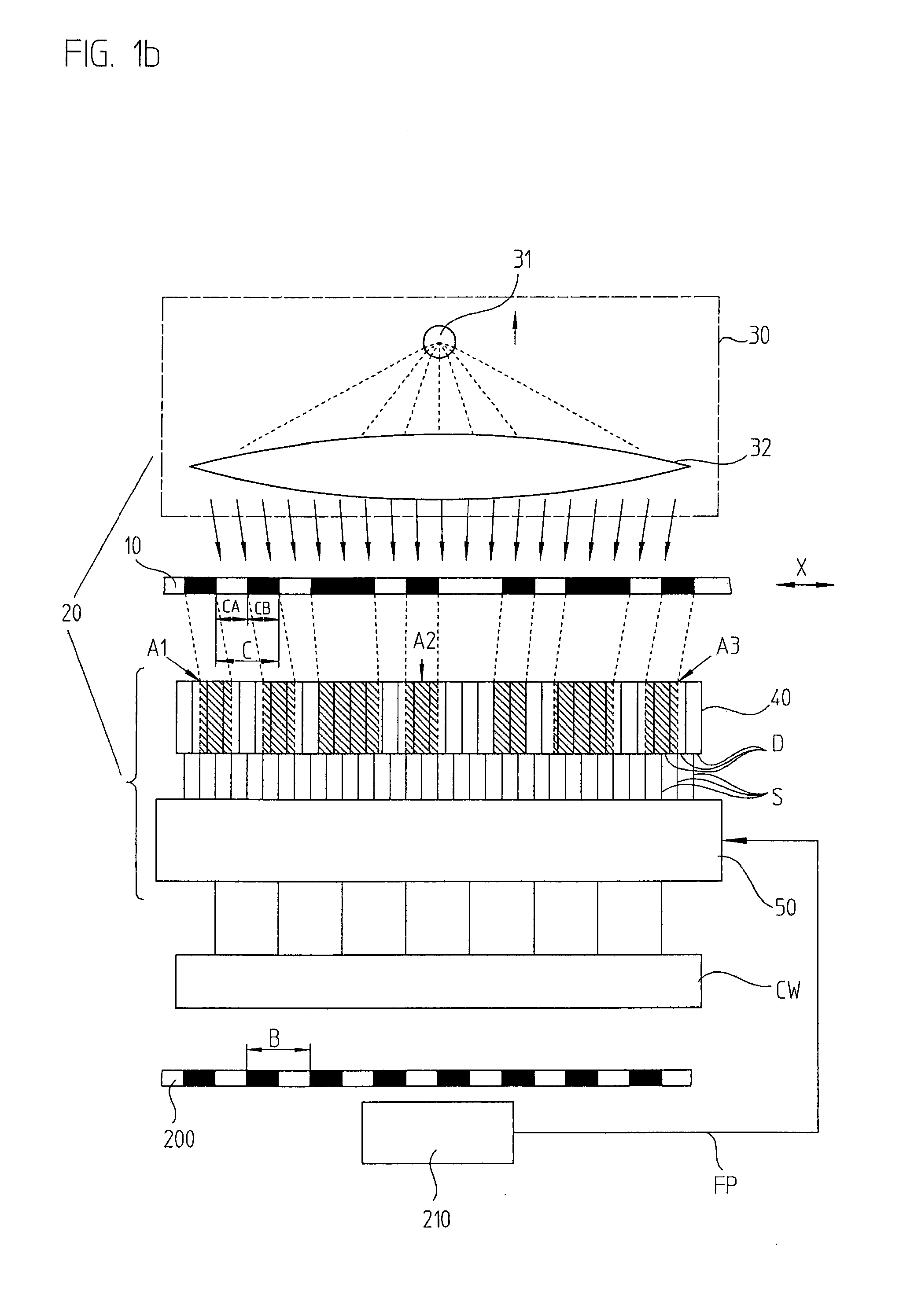
[0034]First of all, FIGS. 1a and 1b clarify how the alignment of the light used for reading a code is able to influence the reliability of the position-value ascertainment. FIG. 1a schematically illustrates an optical position-measuring device, in which a code 10 is scanned by a scanning unit 20 that includes a lighting unit 30, a detector unit 40 and an evaluation unit 50. Code 10 is applied on a measuring standard. For example, the measuring standard may be a scale or a code disk, depending upon whether the position-measuring device is used for measuring linear or rotary positions.

[0035]Code 10 includes a sequence of code elements C of equal length disposed one after the other in measuring direction X, the position information being coded by the optical properties of code elements C. A code 10 of this kind is also referred to as a pseudo random code or PRC for short. For example, the coding may be achieved by forming code elements C to be complementary to each other. In this conte...


PUM


Abstract

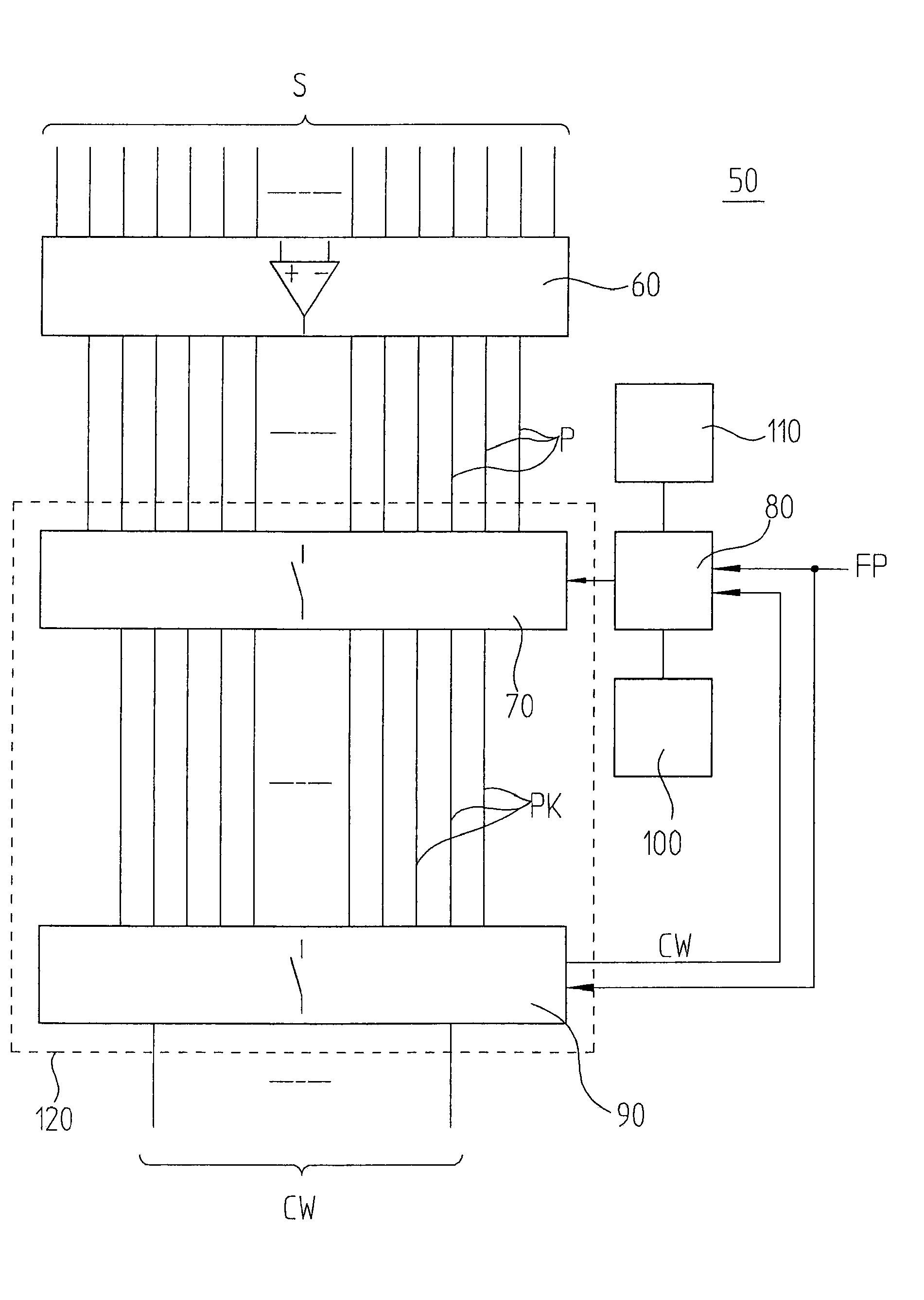
A position-measuring device includes a code and a scanning unit. The code includes a sequence of code elements arranged one after the other in a measuring direction, at least two successive code elements in each case forming one code word having position information. The scanning unit includes a lighting unit for emitting directed light in the direction of the code for imaging at least the code elements forming code word onto a detector unit, the detector unit having in measuring direction at least two detector elements per code element forming code word, as well as an evaluation unit in which the code word having the instantaneous position information is ascertainable from the detector signals of the detector elements. The scanning unit and the code are arranged in a manner allowing movement relative to each other in measuring direction. The detector signals to be evaluated for forming the code word are selectable in the evaluation unit as a function of the imaging of the code elements forming code word onto the detector unit.

Description

CROSS-REFERENCE TO RELATED APPLICATIONS[0001]The present application claims priority to Application No. 10 2007 061 287.9, filed in the Federal Republic of Germany on Dec. 19, 2007, which is expressly incorporated herein in its entirety by reference thereto.FIELD OF THE INVENTION[0002]The present invention relates to a position-measuring device for determining absolute position and to a method for determining absolute position.BACKGROUND INFORMATION[0003]Increasingly in many fields, absolute position-measuring devices are being used, in which the absolute position information is derived from a code track having code elements disposed one after the other in the measuring direction. The code elements are distributed pseudo-randomly, so that in each case a certain number of successive code elements forms a bit pattern. A new bit pattern is formed in response to the shift of the scanning unit in relation to the code track by a single code element, and a sequence of different bit pattern...

Claims


Application Information

Patent Timeline
IPC IPC(8): G01B11/14G06K7/10
CPCG01D5/34792
Inventor OBERHAUSER, JOHANNSCHUERMANN, THOMAS
Owner DR JOHANNES HEIDENHAIN GMBH
Learn More