Field Effect Mode Electro-Optical Device Having a Quasi-Random Photospacer Arrangement

a field effect and electro-optical device technology, applied in the field of field effect mode electro-optical device, can solve the problems of optical interference, user distraction, optical interference that is visible to a user,

Active Publication Date: 2009-06-25
GOOGLE TECH HLDG LLC
View PDF77 Cites 17 Cited by
  • Summary
  • Abstract
  • Description
  • Claims
  • Application Information

AI Technical Summary

Problems solved by technology

While this invention works well in practice, in some configurations the physical properties of the high-resolution display being used can cause optical interference that is visible to a user.
When the photospacers of the optical shutter sufficiently coincide with th...

Method used


Image

  • Field Effect Mode Electro-Optical Device Having a Quasi-Random Photospacer Arrangement
  • Field Effect Mode Electro-Optical Device Having a Quasi-Random Photospacer Arrangement
  • Field Effect Mode Electro-Optical Device Having a Quasi-Random Photospacer Arrangement

Examples


Embodiment Construction

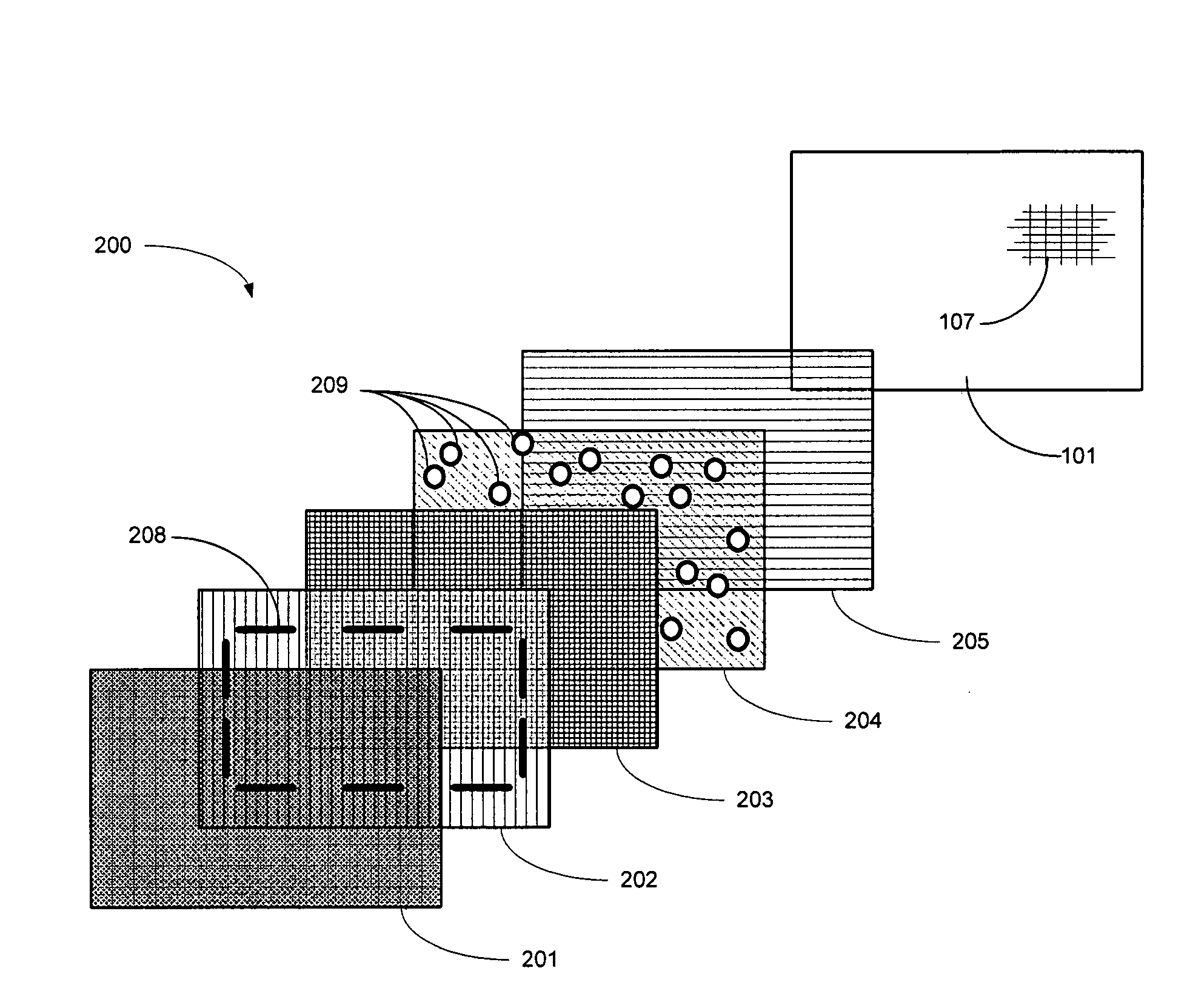
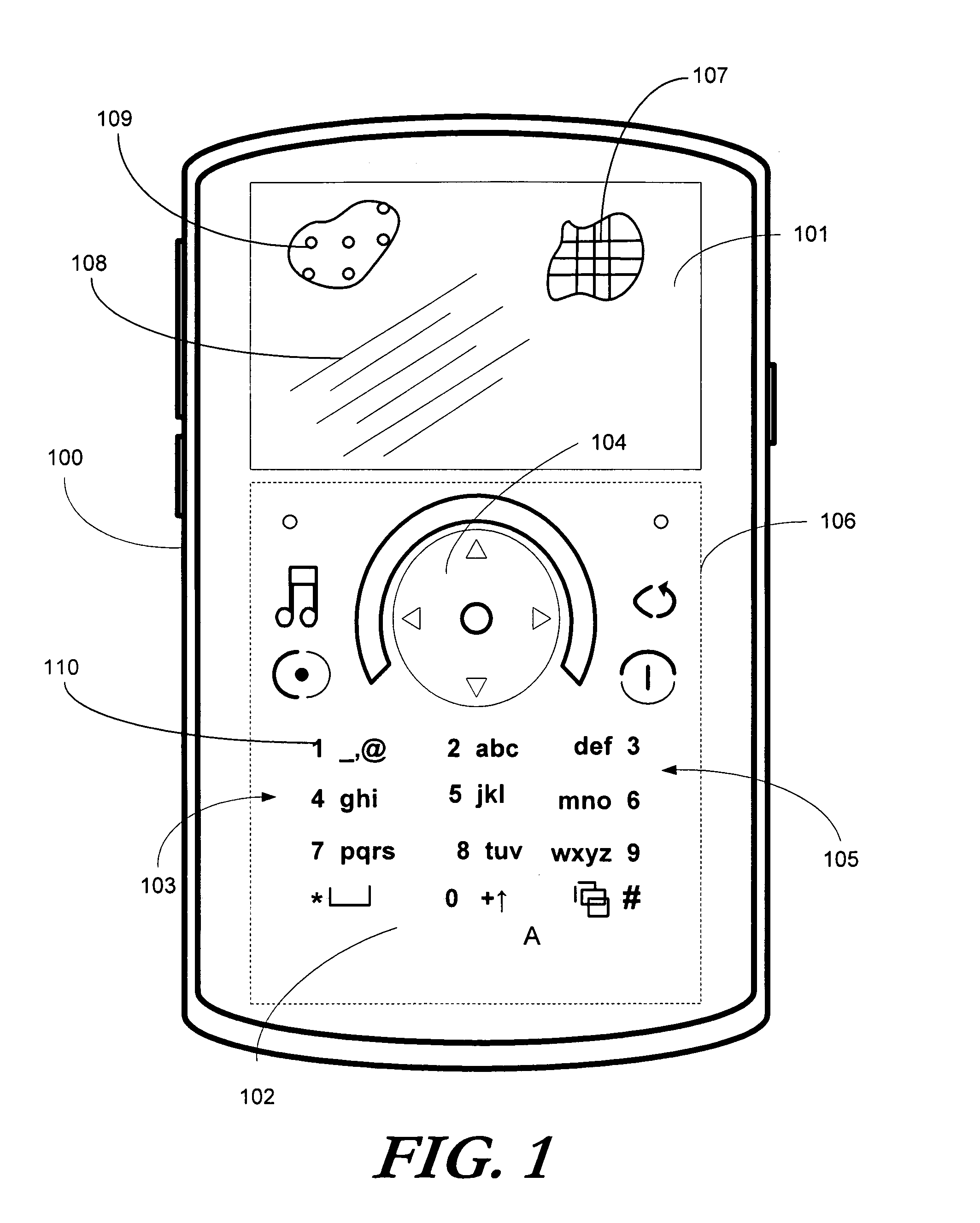
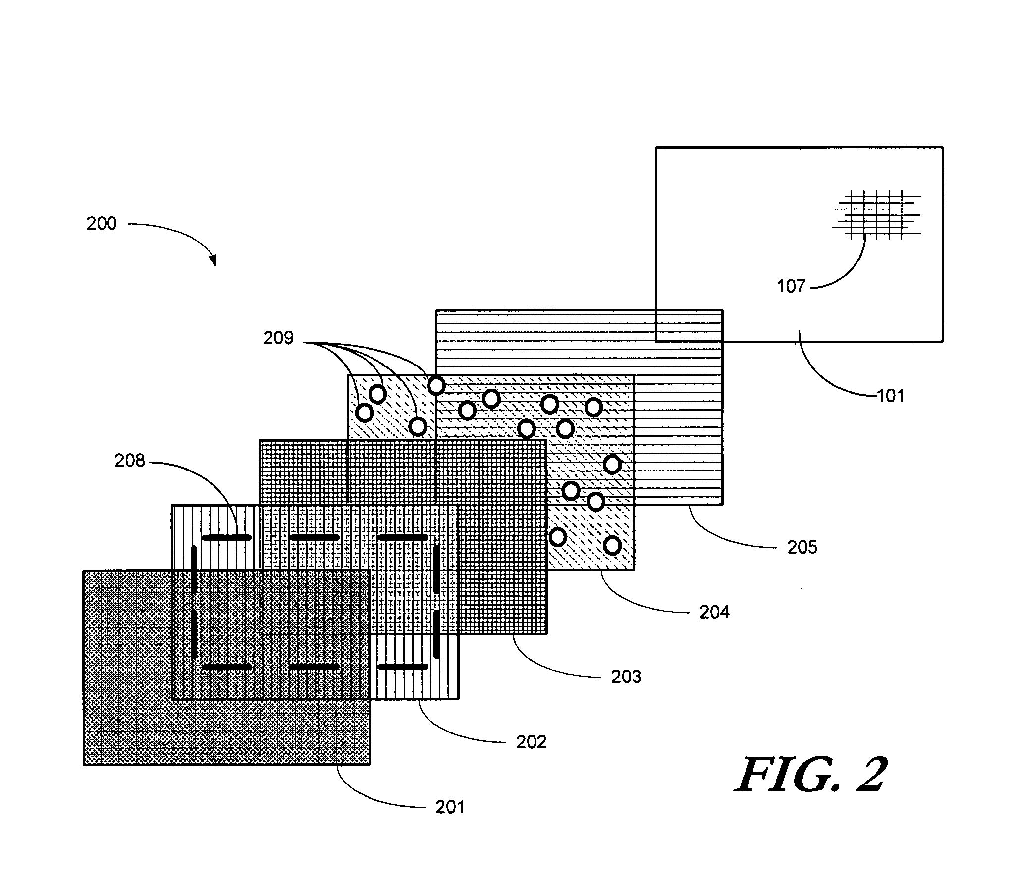
[0015]Embodiments of the invention are now described in detail. Referring to the drawings, like numbers indicate like parts throughout the views. As used in the description herein and throughout the claims, the following terms take the meanings explicitly associated herein, unless the context clearly dictates otherwise: the meaning of “a,”“an,” and “the” includes plural reference, the meaning of “in” includes “in” and “on.” Relational terms such as first and second, top and bottom, and the like may be used solely to distinguish one entity or action from another entity or action without necessarily requiring or implying any actual such relationship or order between such entities or actions. Also, reference designators shown herein in parenthesis indicate components shown in a figure other than the one in discussion. For example, talking about a device (10) while discussing figure A would refer to an element, 10, shown in figure other than figure A. Further, it is expected that one of...


PUM


Abstract

A segmented optical shutter (200) is used with a high-resolution display (101) to provide a dynamic user interface (400) for a portable electronic device (100). To reduce optical interference corresponding to a correlation function for transmitted light occurring between the photospacers (209) in the segmented optical shutter (200) and the black matrix (107), the photospacers (209) are disposed along a light transmitting substrate (204) of the segmented optical shutter (200) in a quasi-random arrangement. The quasi-random arrangement, which may include varying the horizontal and vertical placement of the photospacers (209), repeating asymmetrical subsections of photospacer configurations, varying the size or shape of the photospacers (209), or combinations thereof, misaligns the photospacers (209) relative to the black matrix (107) or other elements to reduce optical interference and moiré patterns that may otherwise be perceptible to a user.

Description

BACKGROUND[0001]1. Technical Field[0002]This invention relates generally to a field effect mode electro-optical device, such as a twisted nematic liquid crystal device, and more particularly to a field effect mode electro-optical device having photospacers that are arranged in an a quasi-random arrangement so as to minimize optical interference with other optical components in a system.[0003]2. Background Art[0004]Copending, commonly assigned U.S. application Ser. No. 11 / 684,454, entitled “Multimodal Adaptive User Interface for a Portable Electronic Device,” teaches a multimodal electronic device that employs a segmented optical shutter enabled dynamic keypad. The segmented optical shutter, which in one embodiment is a twisted nematic liquid crystal display, is used for presenting one of a plurality of keypad configurations to a user. Electric fields are applied to the segmented optical shutter, thereby changing the optical properties of the segments of the optical shutter to hide a...

Claims


Application Information

Patent Timeline
IPC IPC(8): G02F1/1339
CPCG02F1/13392G02F1/134327G02F1/1347G06F3/0238G06F1/1662G06F1/1692G06F1/1626
Inventor EMIG, DAVID M.WEN, CHIEN-HUIZHUANG, ZHIMING
Owner GOOGLE TECH HLDG LLC
Why Eureka
Try Eureka