
Real time acoustic event location and classification system with camera display

a technology of real-time acoustic event and classification system, which is applied in the direction of speech analysis, direction finders, acoustic wave reradiation, etc., can solve the problems of lack of portability necessary for military operations, inability to locate and identify the source of gunfire or shooters in any meaningful way, and inability to carry out military operations. , to achieve the effect of filtering out all other noise sources

Active Publication Date: 2007-04-10
SAFETY DYNAMICS
View PDF20 Cites 68 Cited by
  • Summary
  • Abstract
  • Description
  • Claims
  • Application Information

AI Technical Summary

Benefits of technology

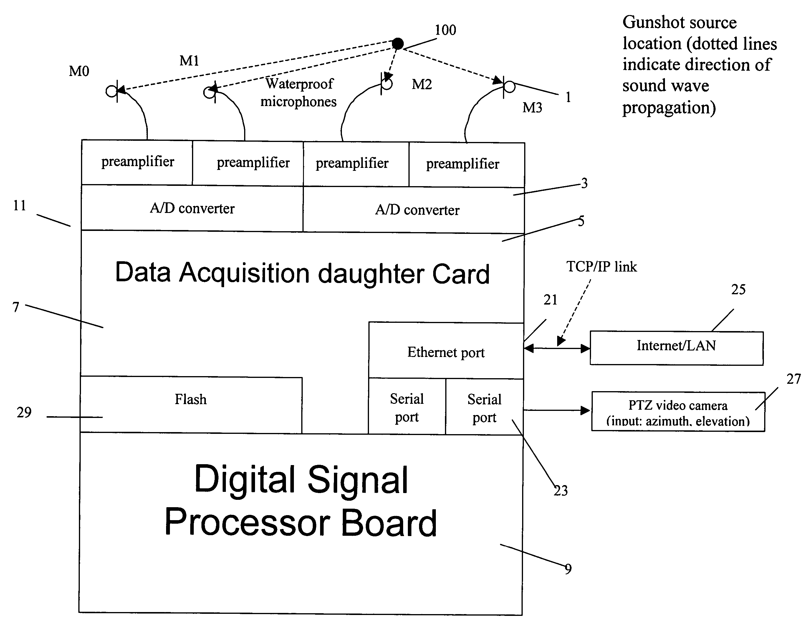
"The gunshot location device uses multiple microphones to detect, locate, and classify gunshots. It can identify the type of gun used and filter out other noise. The device can also calculate the direction and elevation of the gunshot source using a neural network. This information is sent to a video camera, which can orient itself towards the gunshot source and stream a live picture to a display monitor. The device can also log the gunshot incident and its time amplitude waveform onto a nonvolatile memory for interpretation at a later time. Overall, the device provides a more accurate and efficient way to locate and identify gunshots."

Problems solved by technology

In many large cities, gun related violence has become a plague of epidemic proportions.
Unfortunately many of the prior art devices are inadequate to locate and identify the source of gunfire or shooter in any meaningful way, lack portability necessary for military operations, and are too costly to gain acceptance by communities or the military as a tool to combat crime and aid in warfare, respectively.
However, neither Showen et al. nor Baranek et al. teach a method of processing acoustical gunshot data to determine the type of weapon used to fire the gunshot and using a video camera and video signals to locate a shooter.
Furthermore, neither Showen et al nor Baranek et al. teach a gunshot locating system that is portable.
But, the system of Patterson still lacks the portability required to make a gunshot location device practical in military operations, and the system doesn't offer any mechanism for correcting signal processing errors, e.g., false positive gunshot signals or inaccurate weapon determinations.

Method used


Image

  • Real time acoustic event location and classification system with camera display
  • Real time acoustic event location and classification system with camera display
  • Real time acoustic event location and classification system with camera display

Examples


Embodiment Construction

[0017]The invention provides improvements over the art by using fewer, more closely spaced acoustic transducers, for acquiring the source of an acoustic event such as a gunshot and employing a neural network that can be trained to accurately identify the source of the acoustic event. These features will be described with more particularity in FIG. 1 through FIG. 5 below.

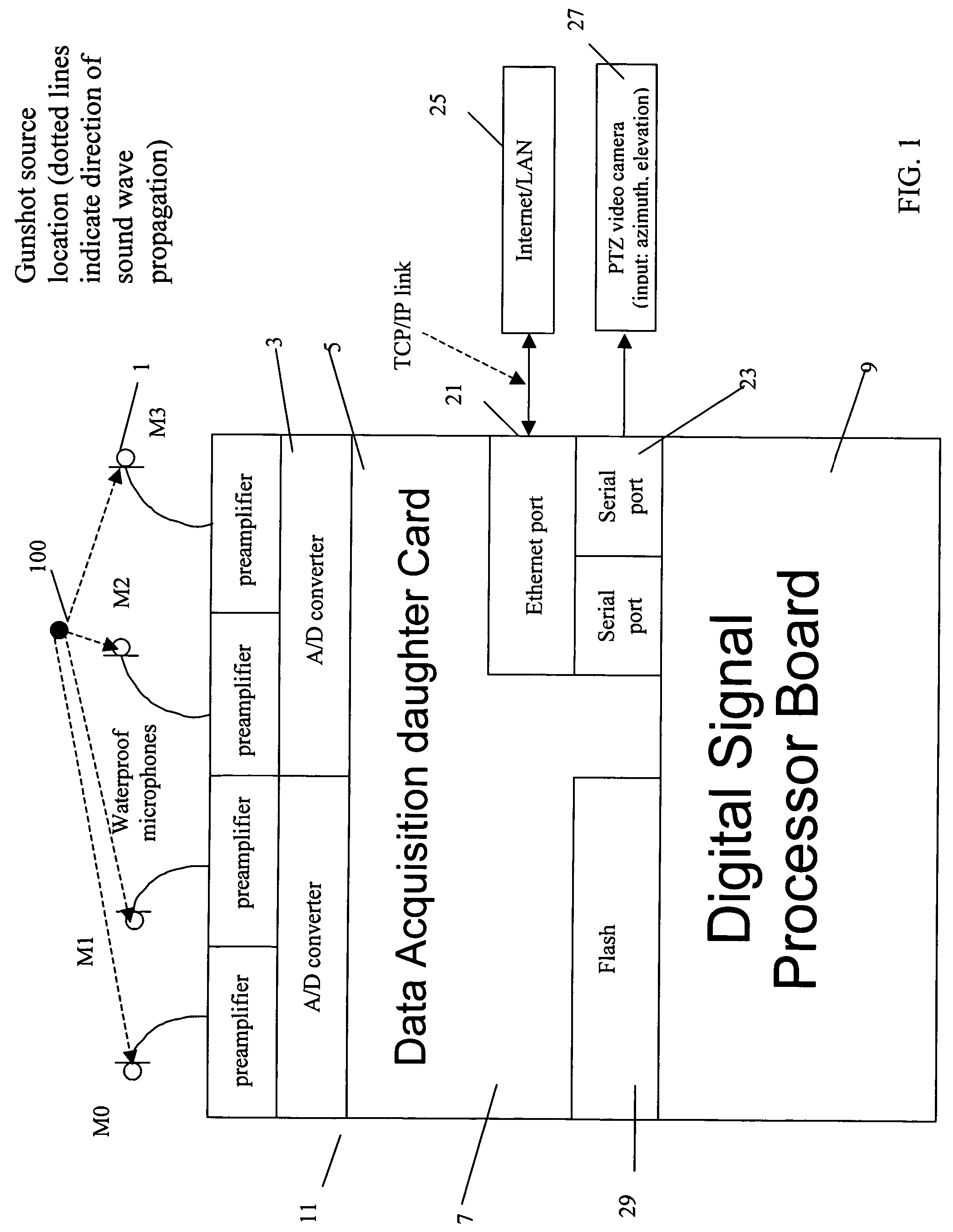
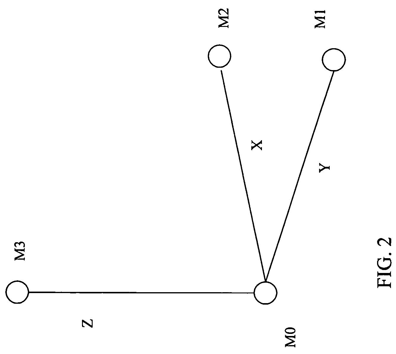
[0018]A gunshot locating device according to one preferred embodiment of the invention described in FIGS. 1 and 3 includes a sensor array 1 for sensing an acoustic event. The sensor array comprises acoustic transducers e.g, microphones, that are placed less than 1.2 feet apart from each other on the vertices of a rectangular tetrahedron. Optimally, four waterproof microphones are used to detect the acoustic signals, with one microphone being the origin microphone, two microphones being the periphery microphones and lying on the base of the rectangular tetrahedron and the fourth microphone lying directly above the ori...


PUM


Abstract

An acoustic event location and classification system comprising an array of at least two acoustic transducers arranged spaced from one another; a central data processing unit for receiving signals from the acoustic transducers and processing the signals to determine a event type and location; and an internet or LAN connection for transmitting event type and location data to a third party, wherein the central data processing unit uses a DSNN to determine the event type and generalized cross correlation functions between microphone pairs to determine the event location.

Description

CROSS-REFERENCE TO RELATED APPLICATION[0001]This application claims priority from U.S. Provisional Application Ser. No. 60 / 669,287 filed Apr. 7, 2005.FIELD OF THE INVENTION[0002]The present invention relates to a system and a method for identifying and locating an acoustic event and providing evidence as to the source of that event. The invention has particular utility as a system for identifying an explosive event, e.g., a gunshot, at a remote location and determining a location of the gunshot, time the gunshot occurred, and identity of the source of the gunshot, e.g., weapon type, weapon caliber, shooter, etc., using a neural network and a triangulation method which runs on a Digital Signal Processor which displays the results of the data acquisition and calculations in real time, and will be described in connection with such utility, although other utilities are contemplated.BACKGROUND OF THE INVENTION[0003]In general there is a long felt need for a system and method to identify ...

Claims


Application Information

Patent Timeline
Patent Type & Authority Patents(United States)
IPC IPC(8): G01S3/80
CPCG01S5/20G01S5/22G01S7/003G01S7/52001Y10S367/906G10L25/30G10L25/51
Inventor BERGER, THEODORE W.
Owner SAFETY DYNAMICS
Learn More