Eureka AIR delivers breakthrough ideas for toughest innovation challenges, trusted by R&D personnel around the world.

Displacement detection apparatus and method

a technology of displacement detection and detection apparatus, which is applied in the direction of instruments, computing, electric digital data processing, etc., can solve the problems of inability to adjust the displacement sensitivity to achieve the desired sensitivity quickly, the fixed displacement sensitivity may not be able to meet the requirements of users, and the user may not be able to perform a tiny movement within the high displacement sensitivity. achieve the effect of improving the operational accuracy

Inactive Publication Date: 2009-06-25
PIXART IMAGING INC
View PDF15 Cites 29 Cited by
  • Summary
  • Abstract
  • Description
  • Claims
  • Application Information

AI Technical Summary

Benefits of technology

[0009]It is an object of the present invention to provide a displacement detection apparatus and method, wherein the displacement sensitivity / resolution can be real-timely and automatically adjusted according to a detected displacement variation so as to improve the operational accuracy.
[0010]It is another object of the present invention to provide a displacement detection apparatus and method, wherein a displacement sensitivity / resolution outputted by the displacement detection apparatus can be larger than, equal to or smaller than a detected displacement sensitivity / resolution so as to increase the practicability of the displacement detection apparatus and method.

Problems solved by technology

However in some circumstances, fixed displacement sensitivity may not be able to fulfill the requirements of users.
For instance, when a user controls the cursor or the aiming point to perform a drawing program requiring fine movement of the cursor or the aiming point, it is difficult to perform a tiny movement within high displacement sensitivity.
However, in most proposed displacement detection apparatuses, adjustment of the displacement sensitivity needs to be operated manually and a user may not be able to adjust the displacement sensitivity to achieve a desired sensitivity quickly.
However, this method can not automatically adjust the displacement sensitivity outputted from the optical pointing device directly according to the detected displacement; therefore it still can not fulfill the requirements of various users.

Method used


Image

  • Displacement detection apparatus and method
  • Displacement detection apparatus and method
  • Displacement detection apparatus and method

Examples


Embodiment Construction

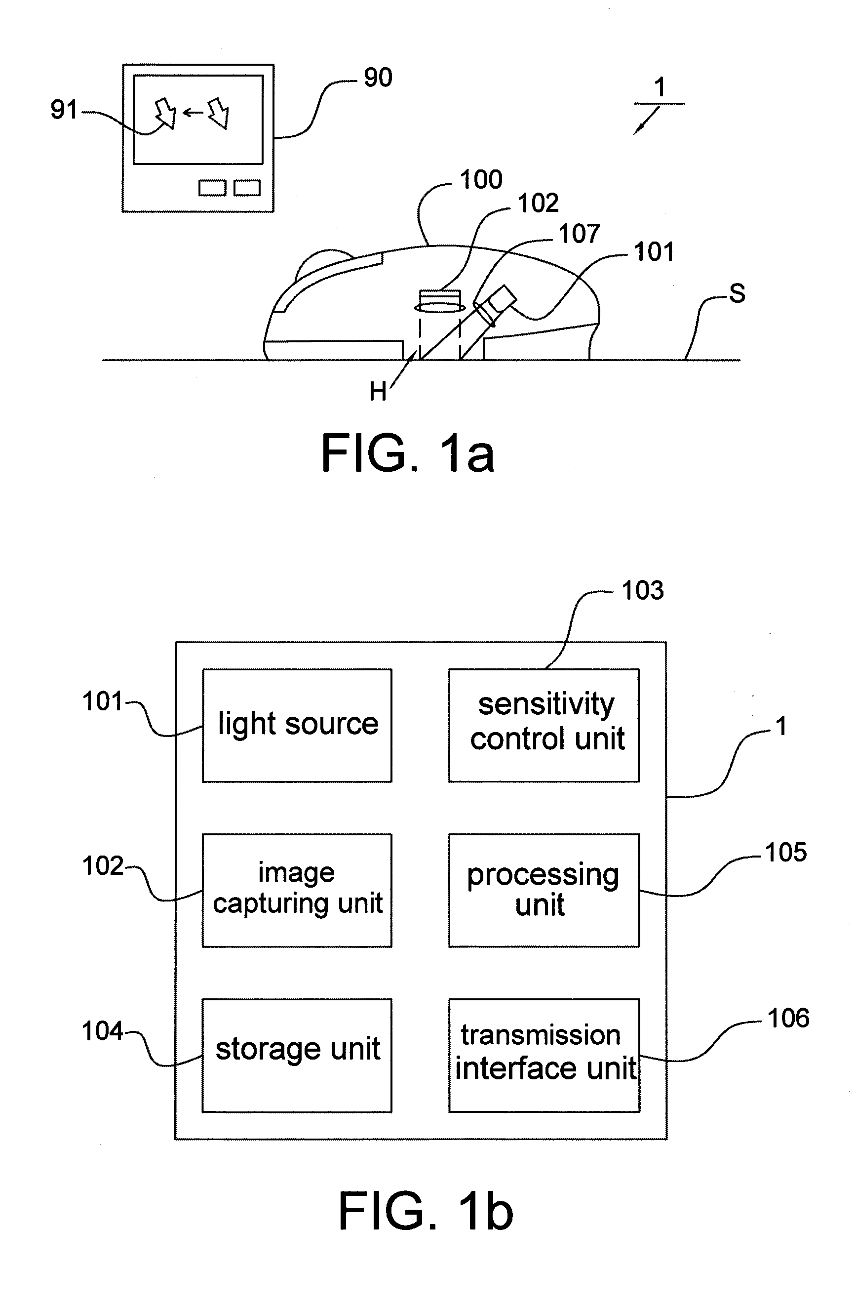
[0024]Referring to FIGS. 1a and 1b, they respectively show a schematic diagram and a block diagram of the displacement detection apparatus 1 according to an embodiment of the present invention. Embodiments of the displacement detection apparatus 1 include an optical mouse and an optical pointing device. The displacement detection apparatus 1 is for controlling the movement of a cursor (or an aiming point) 91 shown on an image display device 90. Firstly, the displacement detection apparatus 1 is exemplarily illustrated with an optical mouse.

[0025]The displacement detection apparatus 1 (an optical mouse herein) generally has a housing 100 with an opening H formed at the bottom surface of the housing 100. Main components of the displacement detection apparatus 1, including a light source 101, an image capturing unit 102, a sensitivity control unit 103, a storage unit 104, a processing unit 105, a transmission interface unit 106 and at lease one lens (or lens set) 107, are disposed insi...


PUM


Abstract

A displacement detection method includes the steps of: capturing a first image and a second image, and obtaining a displacement variation according to the first and the second images; comparing the displacement variation with at least one threshold value; and adaptively adjusting a displacement sensitivity outputted from a displacement detection apparatus according a comparison result of comparing the displacement variation with the threshold value. The present invention further provides a displacement detection apparatus.

Description

CROSS REFERENCE TO RELATED APPLICATION[0001]This application claims the priority benefit of Taiwan Patent Application Serial Number 096149148, filed on Dec. 21, 2007, the full disclosure of which is incorporated herein by reference.BACKGROUND OF THE INVENTION[0002]1. Field of the Invention[0003]This invention generally relates to a displacement detection apparatus and method, and more particularly, to a displacement detection apparatus with adaptively adjustable displacement sensitivity and a method for adaptively adjusting the displacement sensitivity of a displacement detection apparatus.[0004]2. Description of the Related Art[0005]Conventional displacement detection apparatus, such as a mouse or a pointer positioning device, transmits detected displacements to an image display device, e.g. a projection device, a game machine, a personal computer and a television, so as to accordingly control the movement of a cursor or an aiming point shown on the screen of the image display devi...

Claims


Application Information

Patent Timeline
Patent Type & Authority Applications(United States)
IPC IPC(8): G09G5/08
CPCG06F3/03543
Inventor LEE, CHIN CHOUCHEN, HSIN CHIA
Owner PIXART IMAGING INC
Why Eureka
Eureka Blog
Learn More