
Apparatus for selected measurement of, in particular luminescent and/or fluorescent radiation

a technology of luminescent and/or fluorescent radiation and apparatus, which is applied in radiation measurement, instruments, and analysis of materials subjected to chemical reactions, etc., can solve the problems of inability to overcome multi-label measuring instruments, inability to crosstalk samples in adjacent sample wells of microplates, and inability to accurately measure, etc., to achieve high optical efficiency, high optical efficiency, and greater impact

Inactive Publication Date: 2009-06-25
BERTHOLD TECH
View PDF28 Cites 25 Cited by
  • Summary
  • Abstract
  • Description
  • Claims
  • Application Information

AI Technical Summary

Benefits of technology

[0030]This achieves that the light that is emitted from the sample well leaves the reflection chamber largely collimated and is incident perpendicularly on the emission filter. This is advantageous since the action of the filter, particularly of interference filters, is best at a perpendicular beam passage.
[0045]Especially for measuring BRET, FRET, or TR-FRET, it can be advantageous to measure the light intensity in two wavelength ranges simultaneously with two detectors and with the use of different emission filters. In an additional preferred embodiment two detectors are, therefore, provided above the reflector element, whose optical axes (which are the surface normals of the entrance windows) are positioned obliquely to the surfaces of the liquid samples contained in the sample wells. This creates a reflection chamber with two sections, which may be referred to as partial reflection chambers. These partial reflection chambers are preferably paraboloidal in shape.

Problems solved by technology

From European Patent Disclosure EP 0 803 724 A2 a multi-label measuring instrument is known that fails to overcome the above-mentioned problems, primarily because its displaceable mirror block that is designed for all of the measurements does not allow for a highly efficient light passage for detecting weak luminescence signals.
Moreover, in this configuration, crosstalk of samples in adjacent sample wells of the microplate is high.
This leads to incorrect measurement results if a strongly light-emitting sample located next to a weakly light-emitting sample emits so much light that too high a value is measured at the weakly light-emitting sample.
However, the constructional expenses are much higher compared to an embodiment with only a single optical emission light path, particularly if multiple paths must each be provided with their own injectors.
Additional expenses are caused also by the transport mechanism for the detector, and the frequent movements of the highly sensitive detector also carry the risk of damage.
Another significant shortcoming of this optical system is that it is not suitable for the sensitive measurement of chemiluminescence.
Even then it is apparently not possible to inject reagents into the measuring position; nor is it possible in this configuration to perform chemiluminescence measurements with filters, such as BRET or Chroma-Glow.
For reasons of optics, geometric dimensions, availability of lenses with special materials and certain refraction indices, compromises had to be made, if a more or less common optical path is to be used, that led to a reduced performance compared with special instruments, or increased work and expenditures were needed to establish individual measuring light paths that were optimized for the respective measuring method.

Method used


Image

  • Apparatus for selected measurement of, in particular luminescent and/or fluorescent radiation
  • Apparatus for selected measurement of, in particular luminescent and/or fluorescent radiation
  • Apparatus for selected measurement of, in particular luminescent and/or fluorescent radiation

Examples


Embodiment Construction

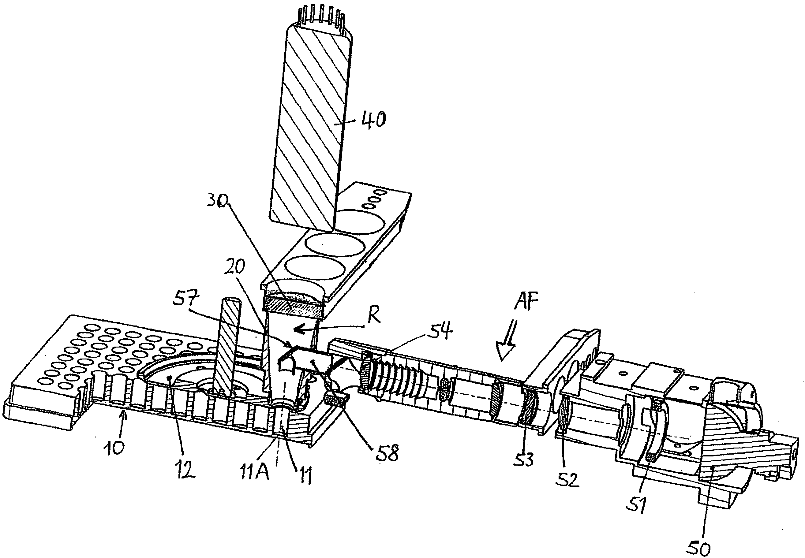
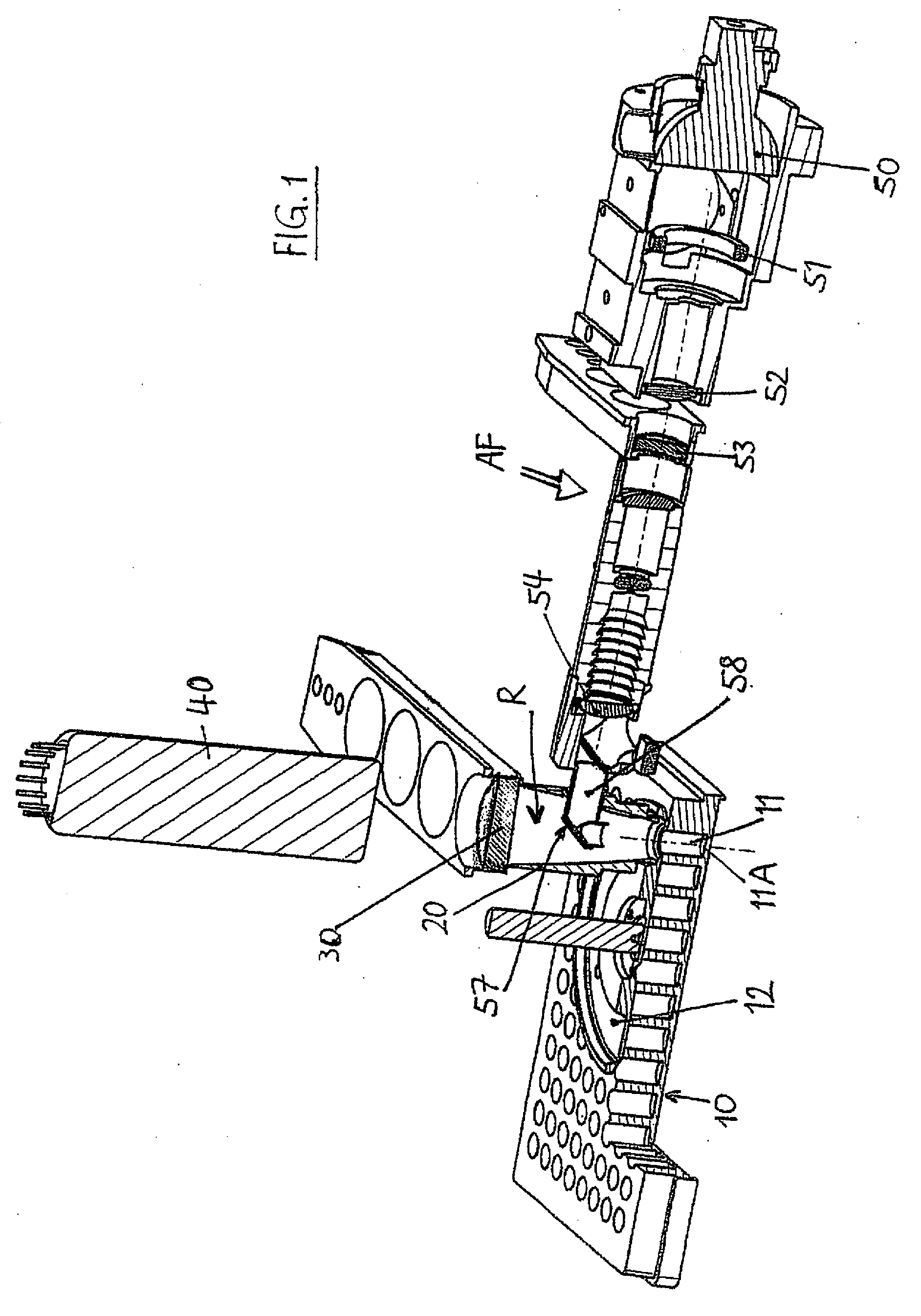
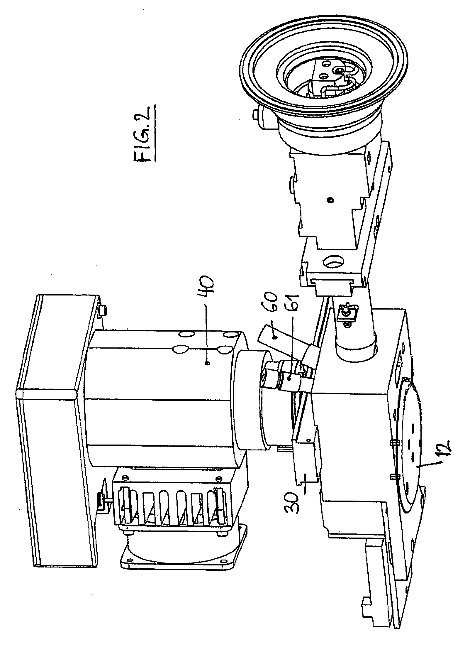
[0066]FIGS. 1 and 2 show the constructional design of the measuring apparatus; FIG. 1 with a microtiter plate 10, FIG. 2 without microtiter plate with an injection element and a laser module. The important components are as follows:

[0067]Disposed above the microtiter plate 10 with its sample wells 11 is a first reflector element 20, whose design will be described in detail further below. The top opening of this first reflector element 20 extends to an emission filter 30, above which a detector 40 for detecting the photons emitted from a sample well is disposed in a manner known per se. Leading from the sample well 11 to the detector 40, accordingly, is the emission light path EF of the emission radiation generated by the sample (not depicted) located in the sample well 11 by fluorescence or luminescence.

[0068]Supported between the first reflector element 20 and the microtiter plate 10 is an aperture wheel 12, whose design substantially corresponds to the European Patent Disclosure E...


PUM


Abstract

An apparatus for selected measurement of at least one of luminescent and fluorescent radiation from at least one sample well, the apparatus comprising: means defining an excitation light path for fluorescence measurements; at least one light source in the excitation path; means defining an emission light path; and at least one detector with a wavelength selector in the emission light path, wherein: the apparatus further comprises at least one first reflector element that encompasses a reflection chamber and projects at least a portion of the light emitted from the at least one sample well directionally onto the wavelength selector; the emission light path extends between the at least one sample well and the wavelength selector through the at least one first reflector element; and the excitation light path extends into the reflection chamber and extends to a point above the at least one sample well.

Description

BACKGROUND OF THE INVENTION[0001]1. Technical Background[0002]In the course of decreasing budgets and difficult cost structure in research, a number of manufacturers of microplate instruments haven gone over to instruments with multiple applications. The goal is to make a multipurpose instrument available to the customer for as many applications as possible, thus eliminating the need to purchase multiple individual instruments. Despite their higher price, compared to a dedicated instrument, these multipurpose instruments are enjoying strong demand. The customer is given the impression that the one purchase makes the purchase of individual instruments superfluous, and that the price of the multipurpose instrument is less than the sum for the dedicated instruments. At present, there are many different instruments, ranging from the “dual-label” instrument for luminescence and fluorescence measurements in the lowest category, through “multi-label readers” with fluorescence, luminescence...

Claims


Application Information

Patent Timeline
IPC IPC(8): G01T1/20
CPCG01J3/02G01J3/0216G01J3/0232G01N21/76G01N21/6445G01N21/6452G01N21/6408
Inventor BERTHOLD, FRITZKLAIBER, NORBERT
Owner BERTHOLD TECH
Learn More