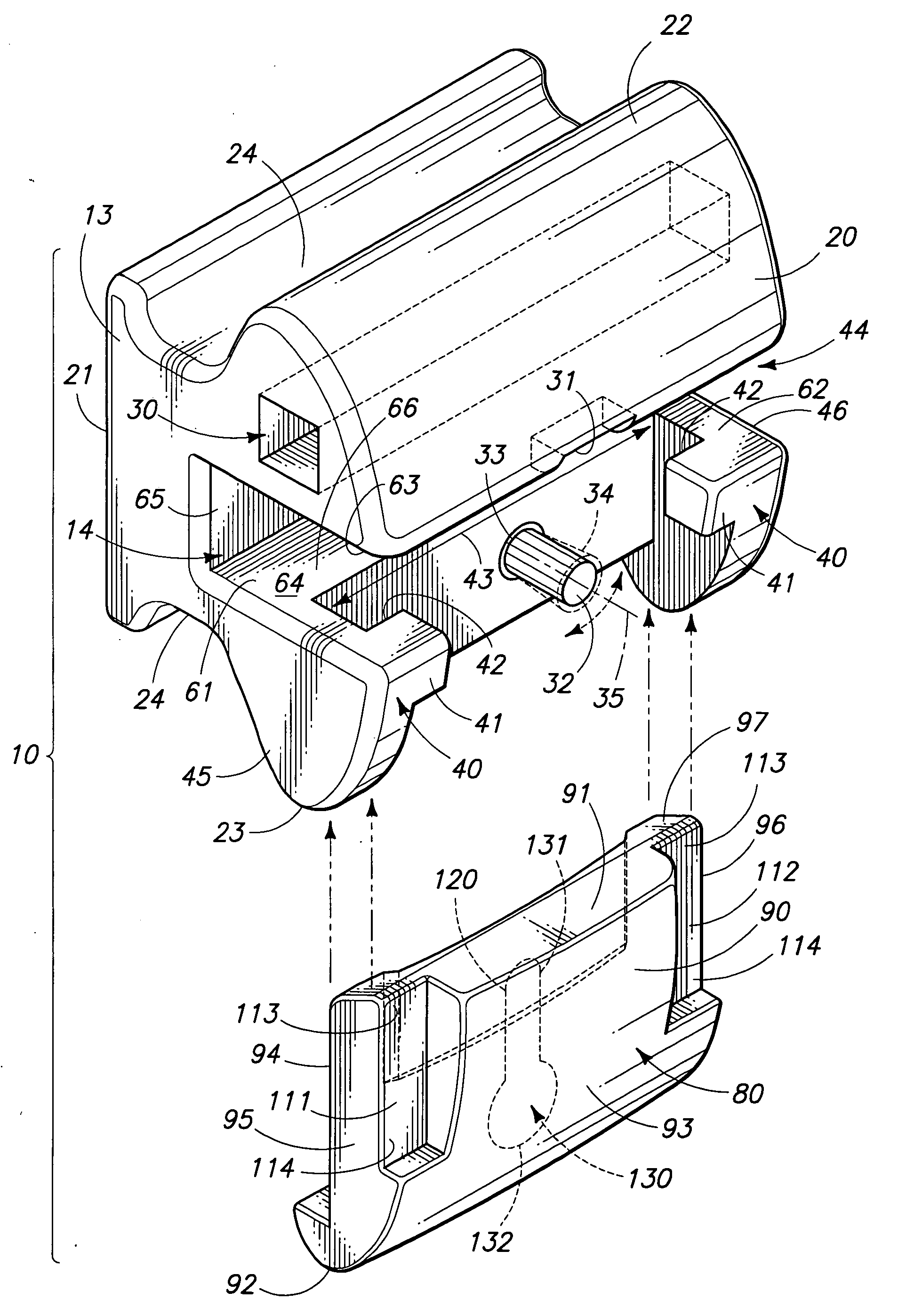
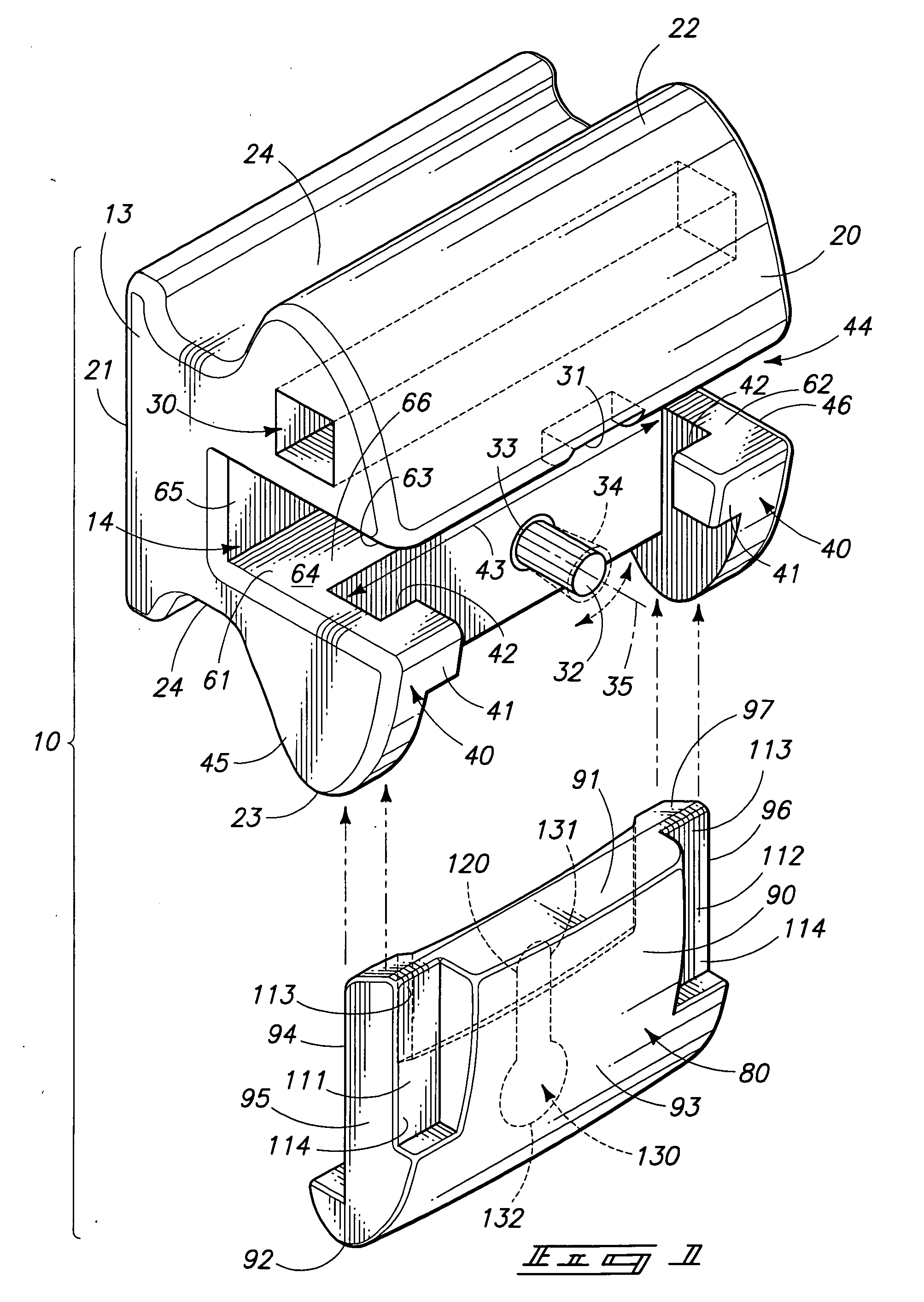
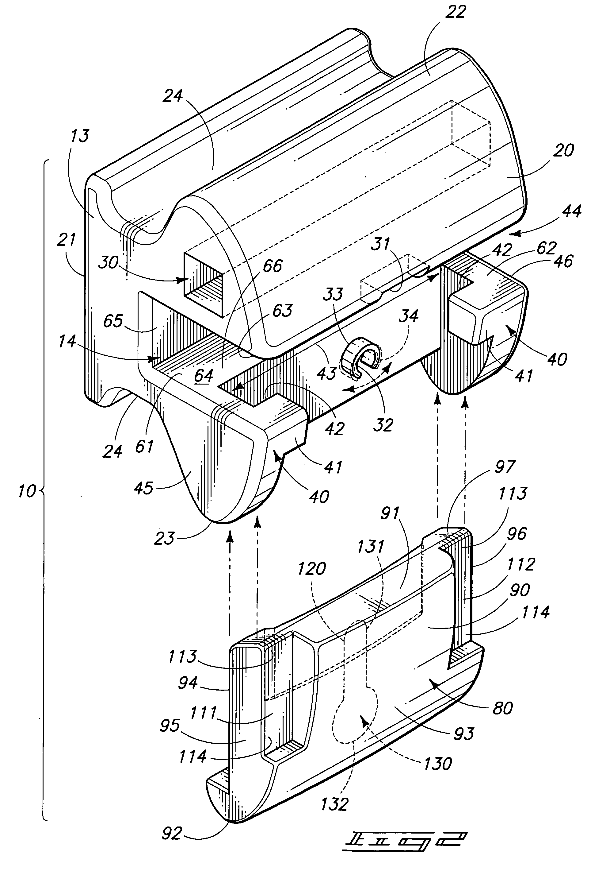
[0010]A first aspect of the present invention relates to an orthodontic bracket which includes a bracket body having an arch wire slot formed therein; and a movable gate which slideably cooperates with the bracket body, and which further is moveable from a first, open position, to a second, closed position, and wherein the movable gate has a posterior facing surface, and an anterior facing surface, and wherein, in the open position, an arch wire is received in the arch wire slot, and wherein a cavity is formed in the posterior facing surface of the gate so as to minimize the frictional engagement of the arch wire by the gate as the gate is moved from the first open position to the second closed position, and which further improves the rotational control of the bracket body.
[0011]Another aspect of the present invention relates to an orthodontic bracket which includes a bracket body having anterior and posterior facing surfaces, and left and right sides, and wherein an arch wire slot having distal ends is formed in the bracket body and extends between the left and right sides of the bracket body, and wherein the arch wire slot has a cross sectional dimension which varies when measured along the arch wire slot, and between the left and right sides of the bracket body; and a gate is slideably borne by the bracket body and is moveable between a first, open position, which permits an arch wire to be received in the arch wire slot, and a second closed position, which captures the arch wire in the arch wire slot in an orthodontic treatment position, and wherein the arch wire slot primarily frictionally engages the arch wire at the distal ends thereof, and in a region adjacent to the left and right sidewalls of the bracket body. This achieves improved rotational control and decreased sliding friction experienced by the bracket body.
[0013]Yet a further aspect of the present invention relates to an orthodontic bracket which includes a bracket body having an anterior and posterior facing surfaces and a width dimension; a substantially transversely disposed arch wire slot formed in the bracket body and which is configured to receive an arch wire therein; and a movable gate which is borne by the bracket body and which is operable when placed in a first, open position, allows the arch wire to be received in the arch wire slot, and wherein the moveable gate has an anterior facing surface, and an opposite posterior facing surface, and wherein the gate slideably cooperates with the bracket body so as to releasably secure the moveable gate in a second, closed position, and which further retains the arch wire in the arch wire slot in an orthodontic treatment position relative to the bracket body, and wherein a portion of the posterior facing surface of the gate forms a cavity such that the arch wire is not substantially frictionally engaged by the moveable gate at it moves between the first, open position to the second closed position, and which further allows for enhanced rotational control across the entire width of the bracket body.
[0014]Moreover, another aspect of the present invention relates to an orthodontic bracket which includes a bracket body having left and right sides, and a width dimension, and wherein an arch wire slot is defined by the bracket body, and extends across the width dimension of the bracket body between the left and right sides thereof, and wherein the arch wire slot is defined by top and bottom surfaces, and a rearward surface which extends between the top and bottom surfaces, and wherein the arch wire slot further has a first end, having a first cross sectional dimension which is located adjacent to the left side of the bracket body, and a second end, having a second cross sectional dimension substantially similar to the first cross sectional dimension, and which is located adjacent to the right side of the bracket body, and wherein the arch wire slot further has an
intermediate region located between the first an second ends thereof, and which has a cross sectional dimension greater than either of the first or second cross sectional dimension; and a slideable gate cooperating with the bracket body, and which has an anterior and a posterior facing surface, and which is moveable between a first, open position, which allows an arch wire to be received in the arch wire slot, and which is further moveable to a second, closed position, which locates the arch wire in an orthodontic treatment position within the bracket body, and wherein a cavity or cavities of different sizes and / or shapes is formed in one of the top, bottom and rearward surfaces which define the arch wire slot, or the posterior surface of the slideable gate, so as to reduce the amount of friction experienced by the arch wire and the gate when the arch wire is located in the orthodontic treatment position and within the bracket body.
[0016]Another aspect of the present invention relates to an orthodontic bracket which includes a bracket body defining an arch wire slot which extends across the width thereof, and wherein the arch wire slot has a first and second end, and an
intermediate region; and a slideable gate moveably cooperating with the bracket body, and which is moveable between a first, open position, which permits an arch wire to be received therein, and a second, closed position, and wherein the bracket body engages the arch wire in the vicinity of the first and second ends of the arch wire slot, and has
minimal contact with the arch wire in the vicinity of the
intermediate region of the arch wire slot. This permits accurate rotational control of the bracket body across its entire width. This also decreases the sliding friction which is created between the bracket body, and the arch wire.
