Protection element

Inactive Publication Date: 2009-06-18
HILTI AG
View PDF14 Cites 0 Cited by
  • Summary
  • Abstract
  • Description
  • Claims
  • Application Information

AI Technical Summary

Benefits of technology

[0012]If a borehole is filled with a glass cartridge, the protection element according to the invention ensures the protection of the operator from the falling-out glass chips.
[0020]Advantageously, the distance of the inner wall from the lead axis decreases in the direction of the bowl opening, at least in some regions. Thus, the inner wall tapers, at least in some regions, toward its free end. The pass-through position is formed advantageously at the free end of the inner wall. When the protection element is pushed on the fastening element, the free rim of the inner wall engages circumferentially the outer profile of the fastening element and seals a possible gap between the free rim of the inner wall and the outer profile of the fastening element. After the end of the setting process of the fastening element, the protection element still can be easily removed, as no exiting mass can adhere to the outer profile of the fastening element in a region between the inner wall of the fastening element and the outer profile of the fastening element. Further, the protection element can be used with fastening elements having different outer diameters.

Problems solved by technology

In particular, at an overhead job, during insertion of a fastening element in a borehole, which is filled with the hardenable mass, the forced-out mass can soil the environment and / or the operator.
The drawback of the above discussed protection element consists in that the mass volume, which is caught by the section of the protection element is very small, and the removal of the protection element after the end of a setting process is rather difficult.

Method used


Image

  • Protection element
  • Protection element
  • Protection element

Examples


Embodiment Construction

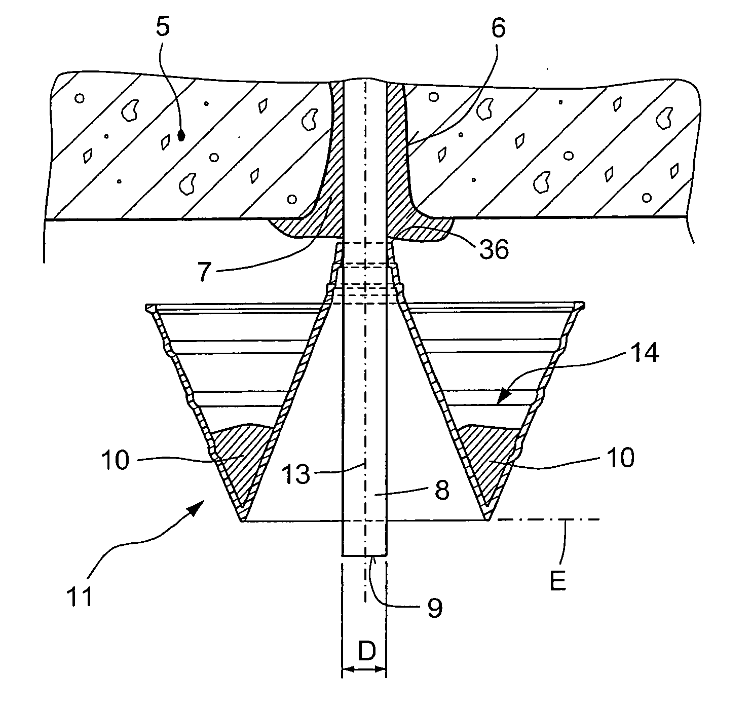
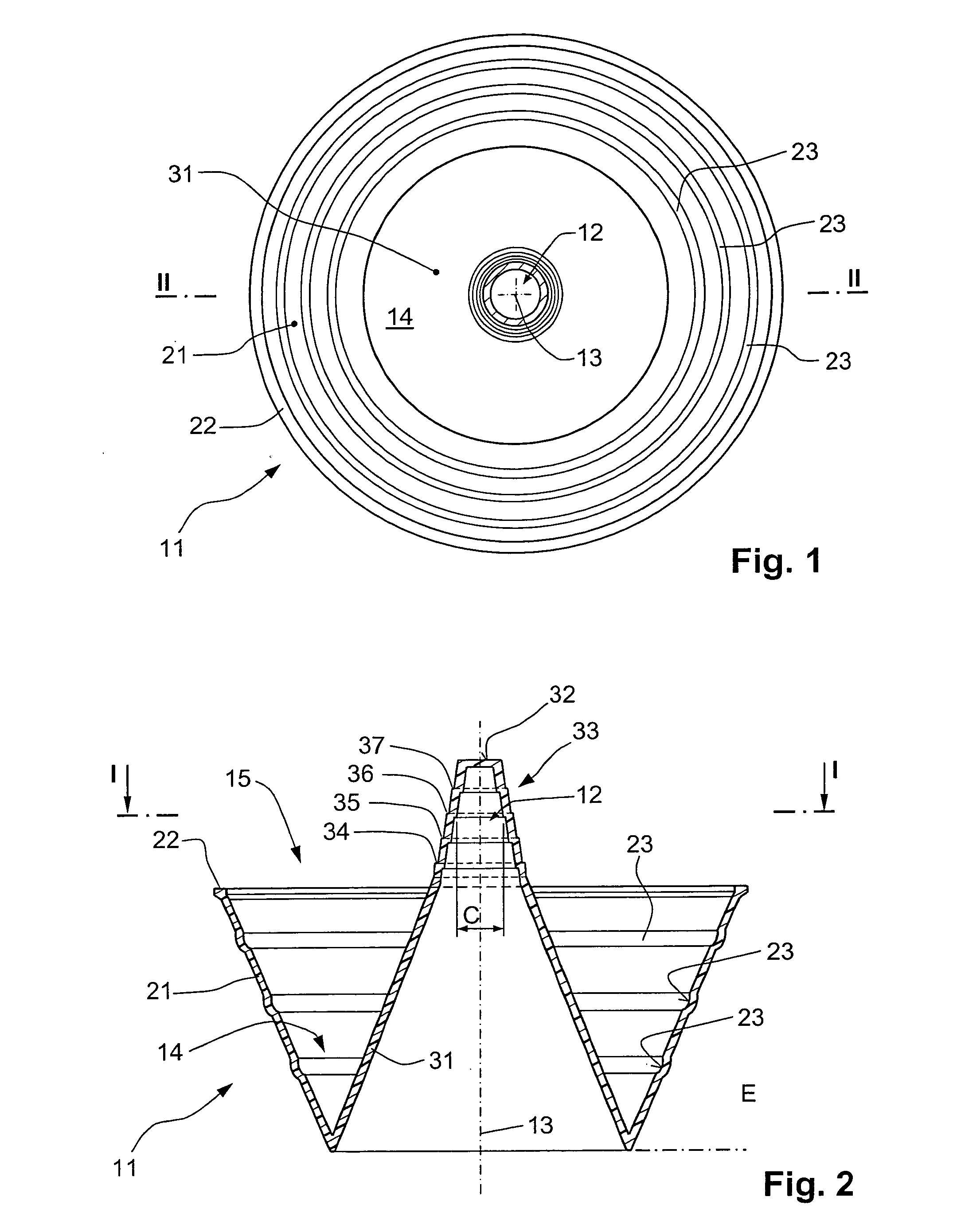
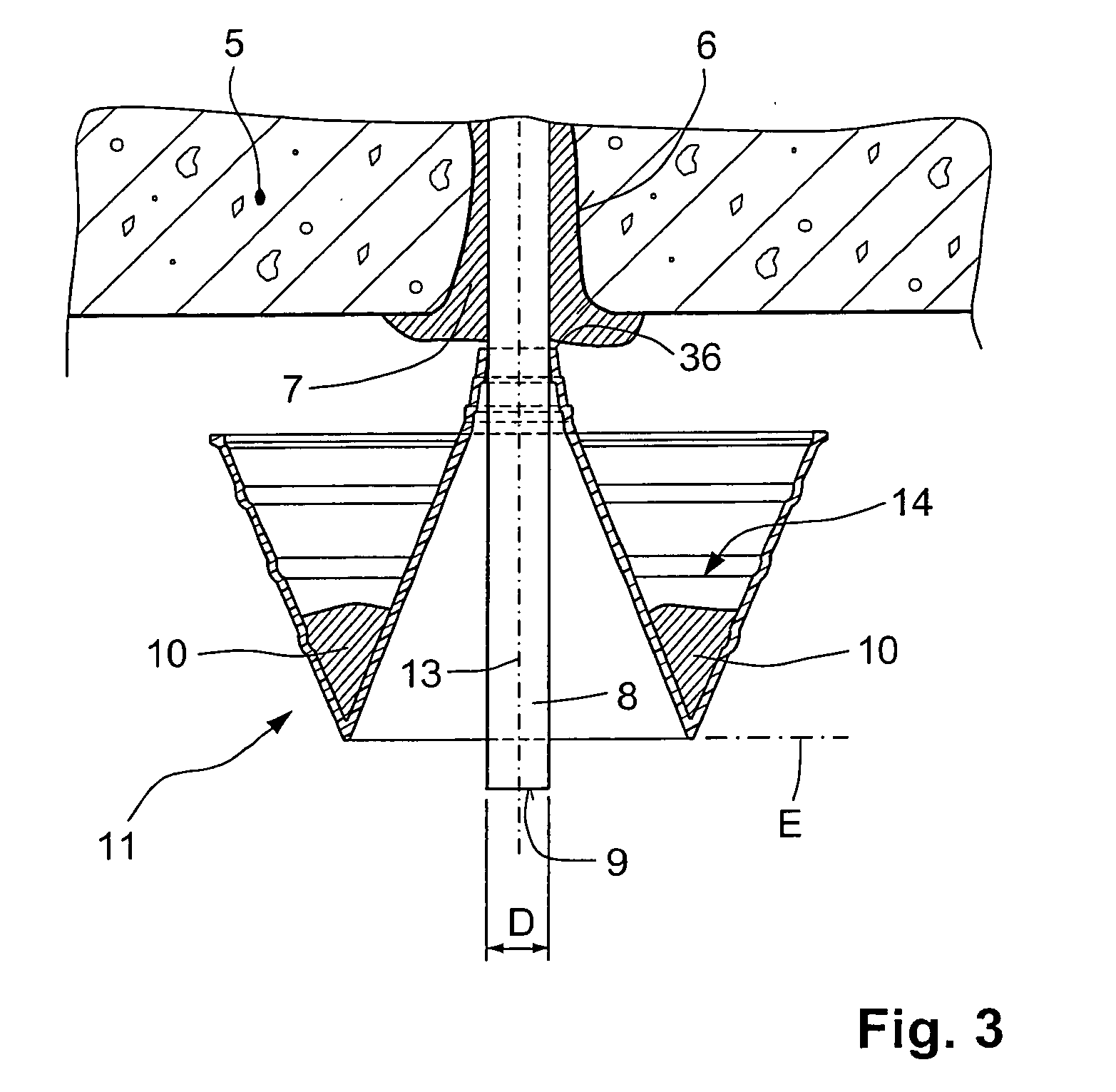
[0027]A protection element according to the present invention, which is shown in FIGS. 1-2, is formed as a bowl-shaped member 11 and has a pass-through position 12 that defines a lead axis 13 for a fastening element, not shown. The bowl shape of the protection element 11 provides a receiving space 14 for a hardenable mass that falls out from a borehole during a setting process. The receiving space 14 is limited by a radial circumferential outer wall 21 coaxial with the lead axis 13 and spaced therefrom. The distance of the outer wall 21 from the lead axis 13 continuously increases toward the bowl opening 15. The outer wall 21 has three reinforcing elements 23 which are formed as radially circumferentially extending grooves.

[0028]The protection element 11 further has a circumferential inner wall 31 coaxial with the lead axis 13 and surrounding the pass-through position 12. The inner wall 31 limits the receiving space 14 radially inwardly. The distance of the inner wall 31 from the le...


PUM


Abstract

A protection element for use with a fastening element (8) anchorable in a hardenable mass and formed as a bowl-shaped member (11) having a circumferential outer wall (21); and a pass-through position (12) for the fastening element (8) and which defines a lead axis (13).

Description

BACKGROUND OF THE INVENTION[0001]1. Field of the Invention[0002]The present invention relates to a protection element for use with a fastening element anchorable in a hardenable mass and having a pass-through position for the fastening element and which defines a lead axis.[0003]2. Description of the Prior Art[0004]Fastening elements such as, e.g., anchor rods, steel studs, and reinforcing iron are anchored in existing constructional components or in bedrock in preliminary formed boreholes which are filled, e.g., with a hardenable mass such as, e.g., mortar or glue.[0005]In particular, at an overhead job, during insertion of a fastening element in a borehole, which is filled with the hardenable mass, the forced-out mass can soil the environment and / or the operator.[0006]German Utility Model DE 94 03 384 U1 discloses a protection element which is formed as splash-guard element that is pushed over a fastening element before the fastening element is inserted in a borehole which is fill...

Claims


Application Information

Patent Timeline
IPC IPC(8): E04B1/41F16B13/14
CPCE21D20/028Y10T403/16F16B13/141
Inventor GLOGGER, JOSEFWOLFF, OLIVERDE SMET, CAMIEL
Owner HILTI AG
Why Eureka
Try Eureka