
High Resolution Time Interpolator

a time interpolator and high resolution technology, applied in the field of timing measurement, can solve the problems of reducing the time to acquire reducing the wait time for acquiring a first valid sample, and excessive non-linearity and limited measurement range, so as to improve the settling time and mirror current matching characteristics, simplify and accelerate the sampling operation, and reduce the wait time

Inactive Publication Date: 2009-06-18
GUIDE TECH
View PDF19 Cites 12 Cited by
  • Summary
  • Abstract
  • Description
  • Claims
  • Application Information

AI Technical Summary

Benefits of technology

[0016]In an exemplary configuration, a high resolution interpolator of both reduced size and cost is provided that provides improved resolution and accuracy to less than 1 picosecond.
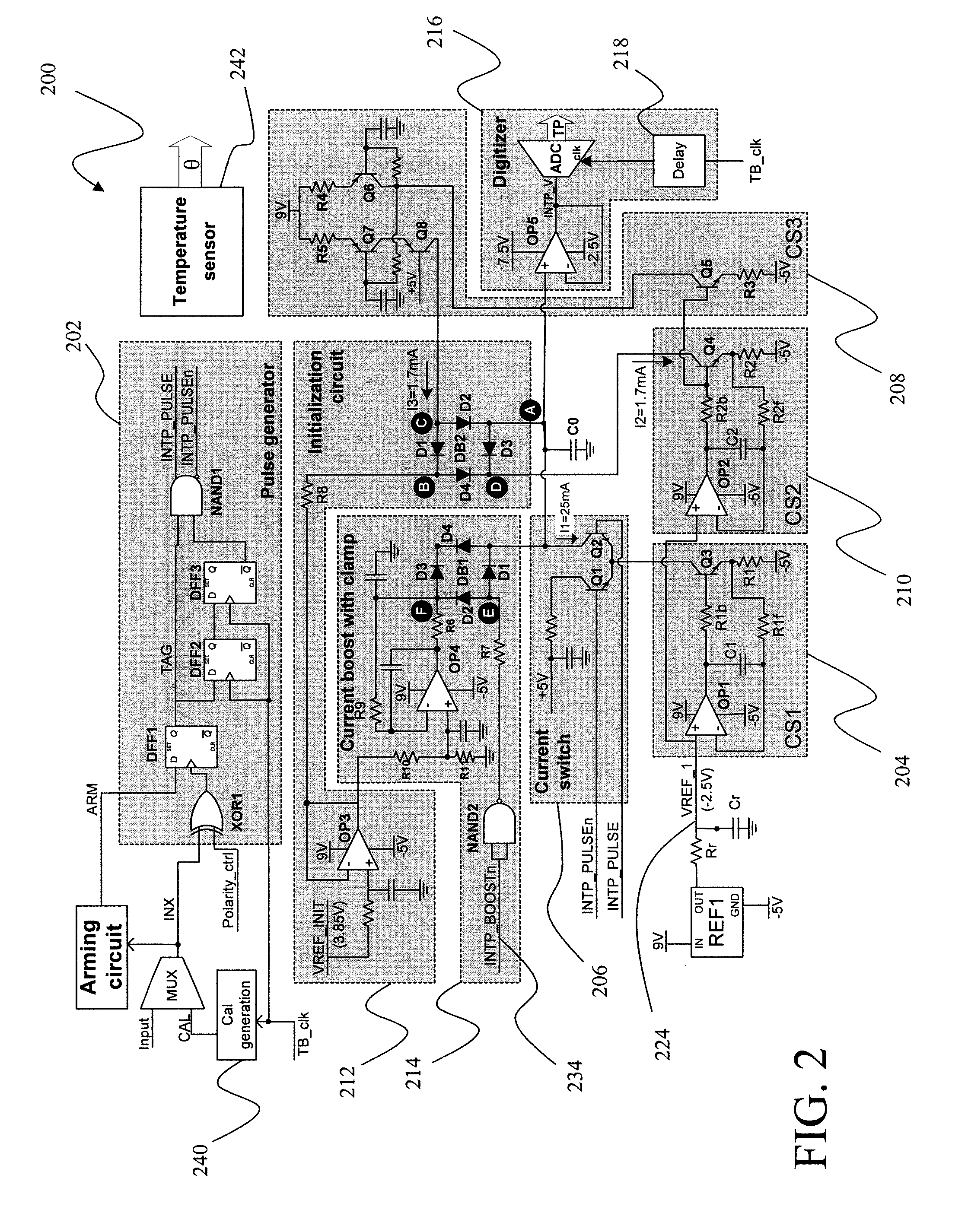
[0018]Another positive aspect of the presently disclosed device is that a current mirror is employed providing improvements in both settling time and mirror current matching characteristics.
[0019]In accordance with aspects of certain embodiments of the present subject matter, high-speed high-resolution ADCs are provided to simplify and accelerate the sampling operation.
[0020]In accordance with yet additional aspects of further embodiments of the present subject matter, ADC wait time to acquire a first valid sample is reduced by clocking the ADC with a delayed version of the timebase clock.

Problems solved by technology

The resolution of such method is usually limited to a few tens of picoseconds.
They provide higher measurement resolution, but may suffer from excessive non-linearity and limited measurement range.
While various implementations of time interpolators have been developed, no design has emerged that generally encompasses all of the desired characteristics as hereafter presented in accordance with the subject technology.

Method used


Image

  • High Resolution Time Interpolator
  • High Resolution Time Interpolator
  • High Resolution Time Interpolator

Examples


Embodiment Construction

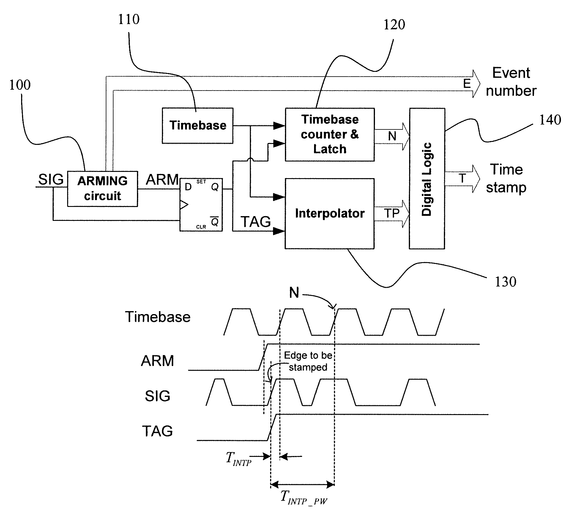
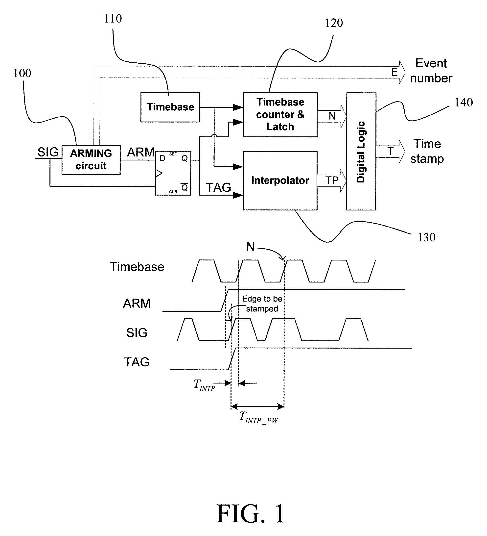
[0029]As discussed in the Summary of the Invention section, the present subject matter is particularly concerned with an improved high resolution interpolator suitable for use with continuous time interval analyzers (CTIA).

[0030]Selected combinations of aspects of the disclosed technology correspond to a plurality of different embodiments of the present invention. It should be noted that each of the exemplary embodiments presented and discussed herein should not insinuate limitations of the present subject matter. Features or steps illustrated or described as part of one embodiment may be used in combination with aspects of another embodiment to yield yet further embodiments. Additionally, certain features may be interchanged with similar devices or features not expressly mentioned which perform the same or similar function.

[0031]The following definitions have been employed in conjunction with the remainder of the description of the present subject matter:[0032]TTB Timebase average ...


PUM


Abstract

The present subject matter is directed to a high-speed high resolution and accuracy time interpolator circuit. The interpolator uses basic dual ramp time-to-digital converter architecture, but provides circuits and methodologies to improve the accuracy, reduce the effective intrinsic jitter, and reduce the measurement time. Improved aspects of the present subject matter correspond to the introduction of a current mirror for improved settling time, a high frequency clock for improved resolution and ADC sample processing to improve resolution and accuracy.

Description

FIELD OF THE INVENTION[0001]The present subject matter relates to timing measurement. More particularly, the present subject matter concerns high accuracy timing in conjunction with Time Interval Analyzer (TIA) methodologies.BACKGROUND OF THE INVENTION[0002]High accuracy timing parameter measurements are necessary to analyze and qualify devices and signals in a wide variety of electronic application. Such applications include clocks, PLLs, serial I / O jitter, skew, etc. A number of strategies have been used in practice for such measurements, including real-time oscilloscopes, equivalent-time oscilloscopes, offset frequency digital or analog under-sampling, and time interval analysis. Although each method has its own pros and cons for specific applications, TIA methods provide fairly general timing / jitter measurement methodologies that provide high accuracy with fast measurement times that cover a wide variety of applications.[0003]TIAs are grouped into two general types: Start-to-Sto...

Claims


Application Information

Patent Timeline
Patent Type & Authority Applications(United States)
IPC IPC(8): G04F10/00
CPCG01R31/31922H03M1/14G04F10/00
Inventor TABATABAEI, SASSAN
Owner GUIDE TECH
Learn More