
Perpendicular magnetic recording head

Inactive Publication Date: 2009-06-18
HITACHI GLOBAL STORAGE TECH NETHERLANDS BV
View PDF5 Cites 19 Cited by
  • Summary
  • Abstract
  • Description
  • Claims
  • Application Information

AI Technical Summary

Benefits of technology

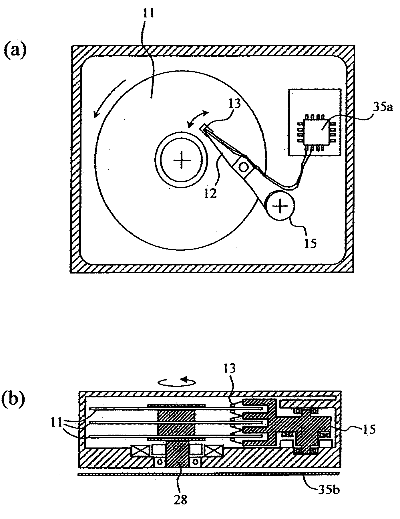
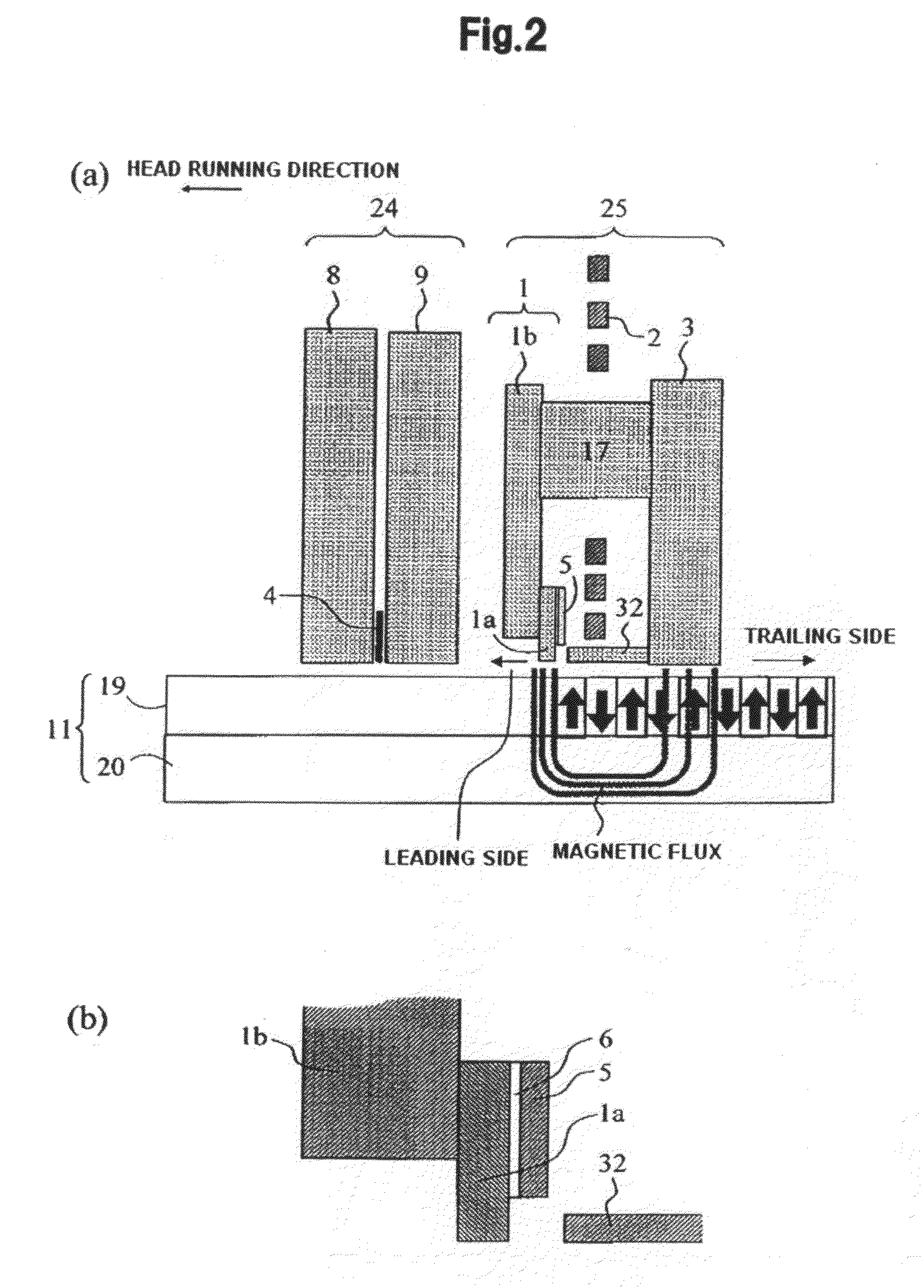
[0006]Embodiments of the present invention provide a magnetic head that can stably supply a perpendicular magnetic field component while generating high recording field strength from a main pole. According to the embodiment shown in FIGS. 2(a) and 2(b), a magnetic body is deposited in a trailing side of a pole tip 1a of a main pole 1 via a nonmagnetic layer 6, so that a second flare section 5 magnetically coupled with each sidewall is provided.

Problems solved by technology

Along with this, thermal fluctuation of magnetization becomes problematic as a cause of an unstable magnetization region of the medium.
Even in the perpendicular magnetic recording method, a single-pole region for writing, which generates a perpendicular recording field to a medium, is narrowed in order to increase surface recording density, and consequently it is being difficult to generate a sufficient perpendicular magnetic field to magnetize a recording medium.
However, the method has a problem that a flare region, which collects a magnetic field generated by induction of a coil, and introduces the magnetic field to the air-bearing surface, is close to an air-bearing surface, consequently recording magnetization width is increased compared with geometric width of a single pole due to field leakage from the flare region.
However, the single-pole head for perpendicular recording is narrowed in shape at an air-bearing surface side to meet the demand for high density recording, which makes it difficult to supply sufficient magnetic field strength to the recording medium.
As a method of increasing magnetic field strength, a method is given, in which a magnetic body is deposited in a trailing side or a leading side at a position retracted from an air-bearing surface of the main pole so as to form an auxiliary pole which supplies auxiliary magnetic flux to the main pole, thereby increasing the magnetic field strength While magnetic field strength can be increased by the method, the method has a problem that magnetic flux flows into a main-pole layer from a region near a tip end portion at an air-bearing surface side of the auxiliary pole, which interferes with a flow of the magnetic flux, and the main pole is affected thereby.

Method used


Image

  • Perpendicular magnetic recording head
  • Perpendicular magnetic recording head
  • Perpendicular magnetic recording head

Examples


Embodiment Construction

[0024]Embodiments of the present invention relate to a magnetic head for a magnetic disk drive using a perpendicular magnetic recording method, and particularly relate to a perpendicular magnetic recording head that generates a recording field perpendicular to a recording medium.

[0025]An object of embodiments of the invention is to provide a perpendicular magnetic recording head, by which writing field strength is increased without affecting a flow of magnetic flux in a main pole, and field gradient is increased, leading to improvement in recording performance, and provide a manufacturing method of the perpendicular magnetic recording head.

[0026]A perpendicular magnetic recording head of an embodiment of the invention has a main pole that applies a magnetic field in a perpendicular direction to a recording medium, an auxiliary pole that absorbs a return field from the recording medium, a coil that allows the main pole to generate an induction field, and a shield disposed at a traili...


PUM


Abstract

Embodiments of the present invention provide a magnetic head that can stably supply a perpendicular magnetic field component while generating high recording field strength from a main pole. According to one embodiment, a magnetic body is deposited in a trailing side of a pole tip of a main pole via a nonmagnetic layer, so that a second flare section is magnetically coupled with each sidewall.

Description

CROSS-REFERENCE TO RELATED APPLICATION[0001]The instant nonprovisional patent application claims priority to Japanese Patent Application No. 2007-323747 filed Dec. 14, 2007 and which is incorporated by reference in its entirety herein for all purposes.BACKGROUND OF THE INVENTION[0002]Recently, demand for high surface recording density is increasing, and a track pitch for writing into a magnetic recording medium and bit size are required to be reduced. Along with this, thermal fluctuation of magnetization becomes problematic as a cause of an unstable magnetization region of the medium. As a method that allows such a problem to be solved, a perpendicular magnetic recording method is given, in which a magnetization signal is recorded in a direction perpendicular to the medium. Even in the perpendicular magnetic recording method, a single-pole region for writing, which generates a perpendicular recording field to a medium, is narrowed in order to increase surface recording density, and ...

Claims


Application Information

Patent Timeline
IPC IPC(8): G11B5/60G11B5/10
CPCG11B5/1278G11B5/3146G11B5/312G11B5/3116
Inventor NUNOKAWA, ISAOSUGIYAMA, MIKITOKUSUKAWA, KIKUOHOSHIYA, HIROYUKI
Owner HITACHI GLOBAL STORAGE TECH NETHERLANDS BV
Learn More