Light source device, projector, and driving method of discharge lamp
a technology of light source device and discharge lamp, which is applied in the direction of electric variable regulation, process and machine control, instruments, etc., can solve the problems of bias consumption of electrodes, and achieve the effect of suppressing the formation of steady convection flow, preventing biased precipitation of electrode materials, and preventing biased consumption of electrodes
- Summary
- Abstract
- Description
- Claims
- Application Information
AI Technical Summary
Benefits of technology
Problems solved by technology
Method used
Image

Examples
first embodiment
[0030]Referring to the drawings, apparatuses as a first embodiment of the present invention such as the light source device are described.
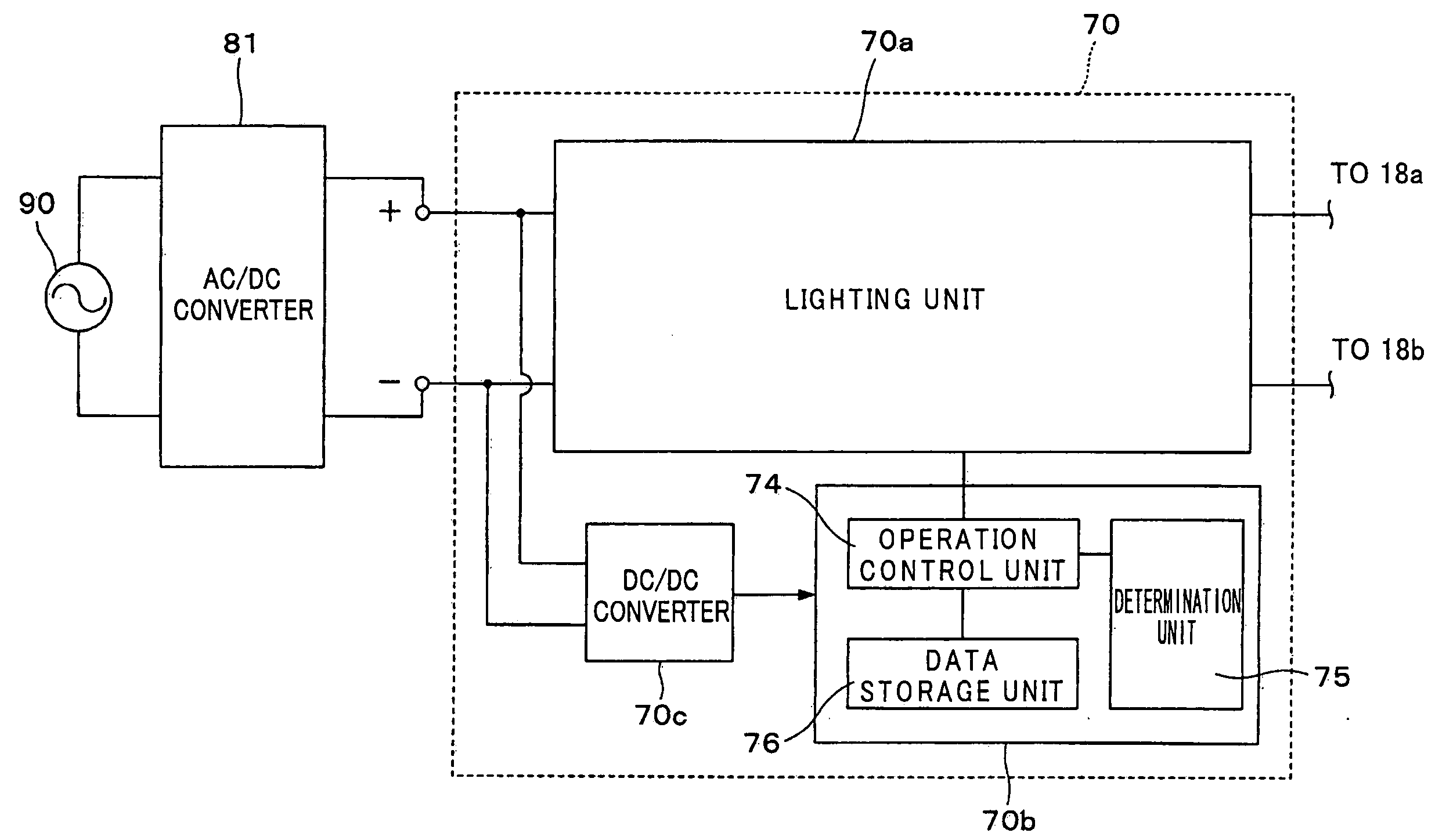
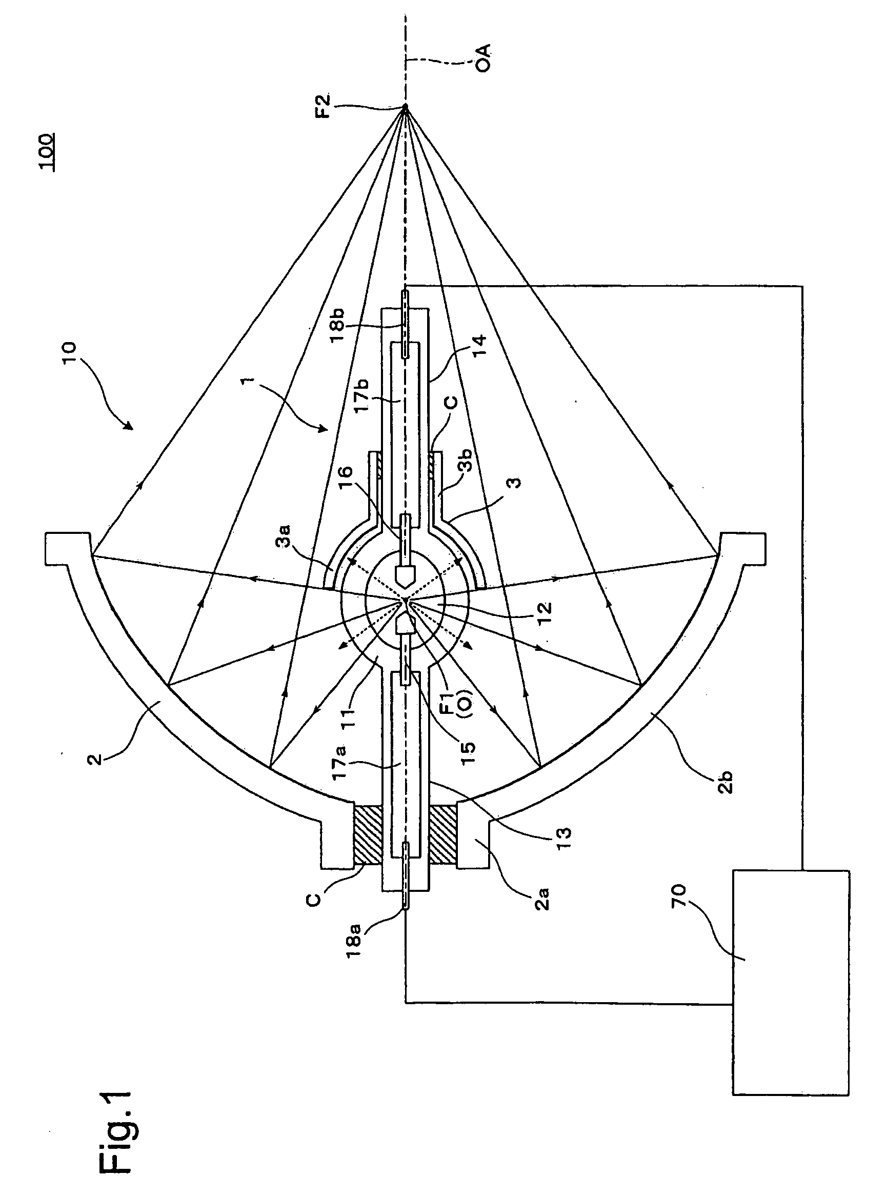
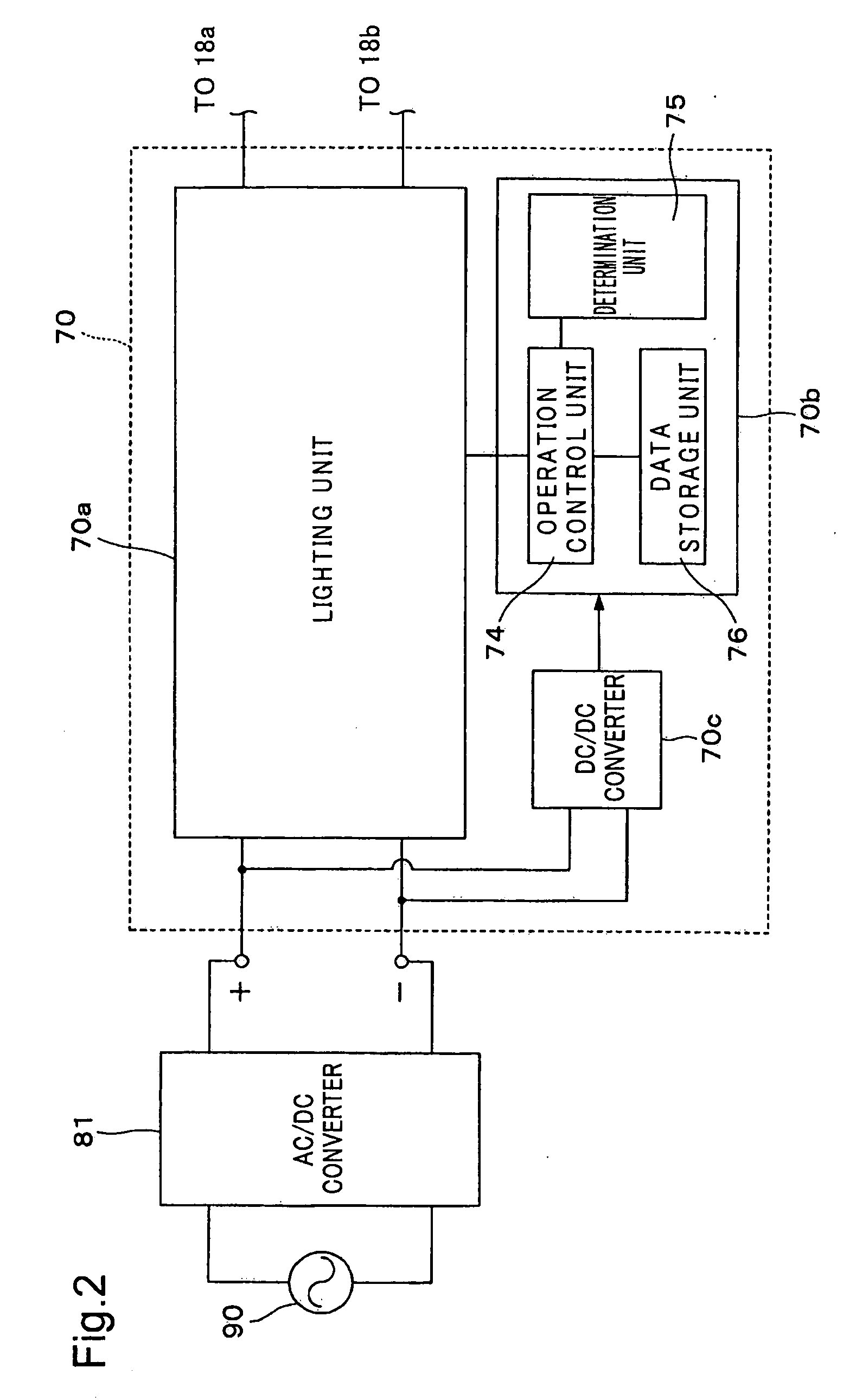
[0031]FIG. 1 is a cross sectional diagram showing a conceptual description of the configuration of the light source device 100. With the light source device 100, the light source unit 10 has a discharge light emission type discharge lamp 1 as a discharge lamp, a reflector 2 which is an elliptic main reflective mirror, and a sub-mirror 3 which is a spherical reflective sub-mirror. As described in detail later, the light source driver 70 is configured as an electrical circuit for controlling light emission in the desired state by supplying alternating current to the light source unit 10.
[0032]In the light source unit 10, the discharge lamp 1 has a tube body 11 constituted by a translucent silica glass tube with the sealed center part bulged in a sphere shape. The light for illumination is emitted from the tube body 11. The discharge lamp 1 also has ...
second embodiment
[0075]Following, the light source device as the second embodiment will be described. Note that the light source device of the second embodiment is a variation of the light source device 100 of the first embodiment, and parts that are not specifically described are the same as those of the light source device 100 of the first embodiment.
[0076]FIG. 9 is a graph for describing the modulation of the duty ratio of the alternating current supplied to the pair of electrodes 15 and 16. The horizontal axis represents time, and the vertical axis represents duty ratio. With this modulation pattern of the alternating current supplied to both electrodes 15 and 16, the section period DP1 for which the first electrode 15 anode duty ratio is greater than or equal to 50% where the first electrode 15 anode period is relatively long, and the section period DP2 for which the first electrode 15 anode duty ratio is less or equal to 50% where the second electrode 16 anode period is relatively long are alt...
third embodiment
[0083]Following, the light source device of the third embodiment will be described. Note that the light source device of the third embodiment is a variation of the light source device 100 of the first embodiment, and parts not specifically described are the same as the light source device 100 of the first embodiment.
[0084]FIG. 13 is a graph for describing the modulation of the duty ratio of the alternating current supplied to the pair of electrodes 15 and 16. The horizontal axis represents time, and the vertical axis represents the duty ratio. In this case, the modulation pattern of the alternating current supplied to both electrodes 15 and 16 consists of the anterior half period H1 for which the first electrode 15 anode duty ratio is greater than or equal to 50% where the anode period of the first electrode 15 is relatively long, and the posterior half period H2 for which the first electrode 15 anode duty ratio is less or equal to 50% where the anode period of the second electrode ...
PUM
 Abstract
Description
Claims
Application Information
 - R&D
- Intellectual Property
- Life Sciences
- Materials
- Tech Scout
- Unparalleled Data Quality
- Higher Quality Content
- 60% Fewer Hallucinations
Browse by: Latest US Patents, China's latest patents, Technical Efficacy Thesaurus, Application Domain, Technology Topic, Popular Technical Reports.
© 2025 PatSnap. All rights reserved.Legal|Privacy policy|Modern Slavery Act Transparency Statement|Sitemap|About US| Contact US: help@patsnap.com