
Color filter ink, color filter ink set, color filter, image display, and electronic apparatus

a color filter and ink technology, applied in the field can solve the problems of pigment yellow 150 not being stably dispersed in ink, unfavorable material saving in photolithography process, increased production cost of color filter inks, etc., and achieve excellent discharging stability, wide color reproduction range, and long-term stability of pigment dispersion

Inactive Publication Date: 2009-06-18
SEIKO EPSON CORP
View PDF15 Cites 6 Cited by
  • Summary
  • Abstract
  • Description
  • Claims
  • Application Information

AI Technical Summary

Benefits of technology

[0009]An advantage of the present invention is to provide a color filter ink discharged by an inkjet method, in which the color filter ink exhibits an excellent long-term stability in pigment dispersion (dispersion stability) and an excellent discharging stability, as well as can be suitably used to produce a high contrast color filter that enables image display in a wide color reproduction range, suppression of unevennesses of color and density at respective portions, and an excellent uniformity in characteristics among individual filters. Another advantage of the invention is to provide a color filter ink set including the color filter ink. Still another advantage of the invention is to provide the color filter that exhibits the above advantageous effects. And yet still another advantage of the invention to provide an image display and an electronic apparatus that include the color filter.
[0010]The above advantages are accomplished by aspects and preferred features of the invention described below.
[0011]According to a first aspect of the invention, there is provided a color filter ink used to produce a color filter by using an inkjet method. The color filter ink includes: C. I. pigment yellow 150; and a sulfonated pigment derivative represented by following chemical formula 1:where n represents an integer of 1 to 5, and X1 to X8 each independently represent a hydrogen atom or a halogen atom.
[0012]In this manner, there can be obtained a color filter ink that is discharged by an inkjet method and that exhibits an improved long-term stability of pigment dispersion (the dispersion stability) and an improved discharging stability. Additionally, the color filter ink obtained can be suitably used to produce a color filter having a high contrast ratio, achieving display of color images with a wide color reproducibility, having the suppressed unevennesses of color and density at respective portions of the filter, and showing the excellent uniformity of characteristics among individual filters.
[0013]Preferably, in the color filter ink according to the first aspect, an inequality expressed by 0.005≦XPD / XPY150≦0.32 is satisfied, where XPD (wt %) represents a content of the pigment derivative in the color filter ink and XPY150 (wt %) represents a content of the C. I. pigment yellow 150 in the color filter ink.
[0014]In this manner, a long-term dispersion stability of pigment particles in the color filter ink can be especially improved, as well as brightness and contrast of the colored portions formed with the color filter ink can be significantly increased.

Problems solved by technology

Accordingly, a production cost of the color filter is increased, as well as using such a photolithography process is unfavorable in terms of material savings.
However, the C.I. pigment yellow 150 cannot be stably dispersed in ink.
In that case, if liquid droplets (ink) are discharged for long hours or continuously discharged, mist contamination of ink or the like occurs near nozzles and changes a flying route of a discharged droplet (a so-called flight deviation), thereby inhibiting the droplet from landing at a target position, or causes clogging of droplet discharging heads, thereby resulting in problems such as instability of the amounts of droplets discharged.
Additionally, due to unstable dispersibility of the C.I. pigment yellow 150, aggregation of ink can easily occur, which can hinder micro-dispersion of the pigment.
For example, the apparatuses for industrial use are operated in a mass production of color filters or discharging of droplets on a large work sheet (a substrate), and thus are required to discharge a large amount of droplets for long hours.
The apparatuses, which are used under such a tough condition, often cause fluctuation of discharging amounts of droplets as compared to those for general use.
Those problems result in color unevenness, density unevenness, and the like at portions of a color filter produced, or cause variations of characteristics (particularly, color-related characteristics such as a contrast ratio and a color reproduction range) among multiple color filters produced.
Thereby, the produced color filters are less reliable.

Method used


Image

  • Color filter ink, color filter ink set, color filter, image display, and electronic apparatus
  • Color filter ink, color filter ink set, color filter, image display, and electronic apparatus
  • Color filter ink, color filter ink set, color filter, image display, and electronic apparatus

Examples


first embodiment

[0267]A color filter according to a first embodiment will be described below

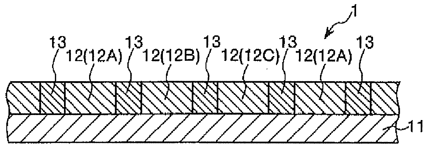
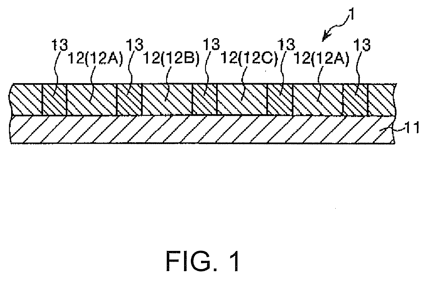
[0268]FIG. 1 is a sectional view showing the color filter according to the first embodiment.

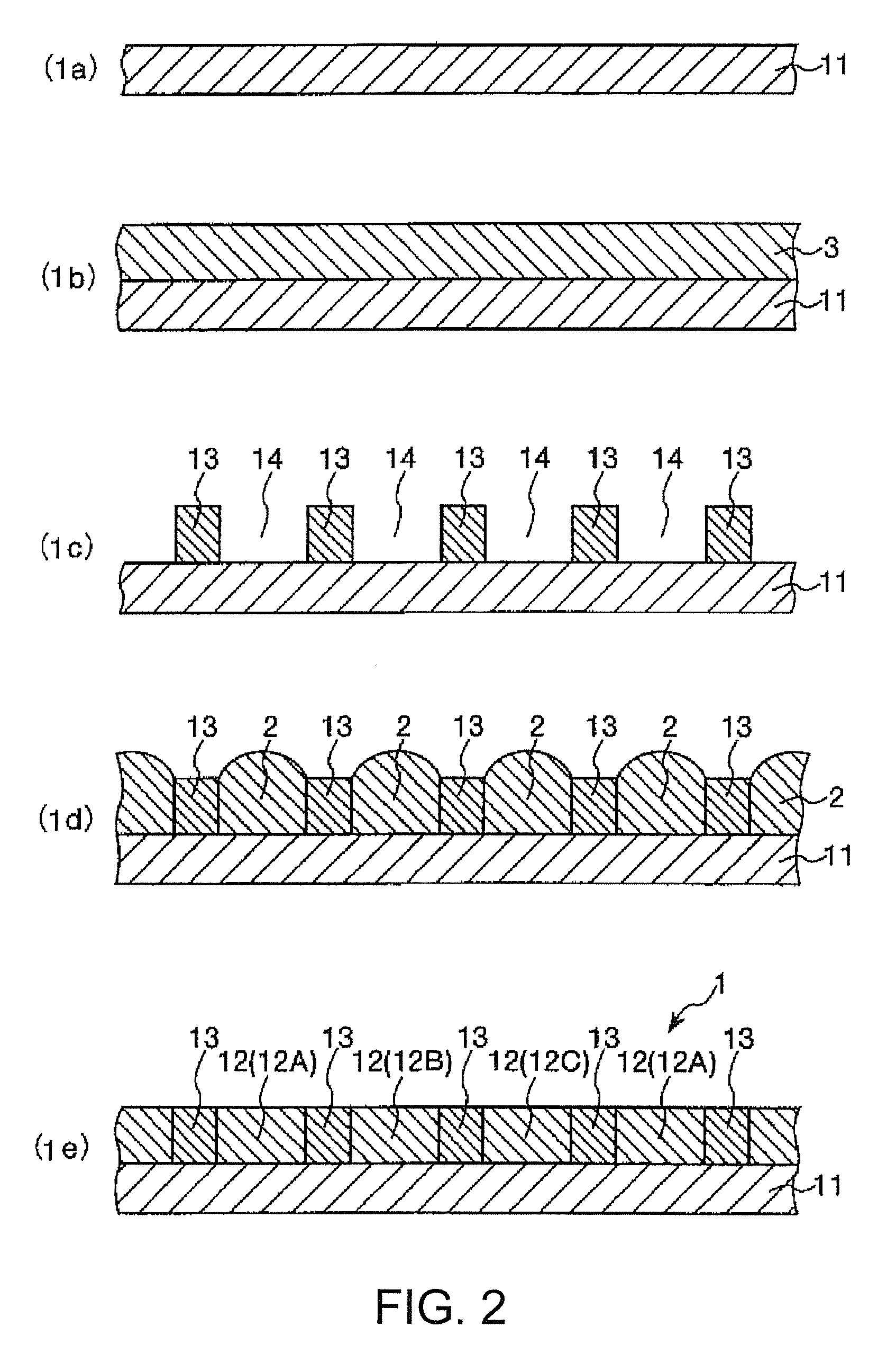
[0269]As shown in FIG. 1, a color filter 1 includes a substrate 11 and colored portions 12 formed with the above-described color filter ink (the ink set). The colored portions 12 include a red colored portion (a first colored portion) 12A formed with the color filter ink of the embodiment (the red ink) including the C.I. Pigment Yellow 150, the above-described sulfonated pigment derivative, and at least one red pigment; a green colored portion (a second colored portion) 12B formed with the color filter ink of the embodiment (the green ink) including the C.I. Pigment Yellow 150, the sulfonated pigment derivative, and at least one green pigment; and a blue colored portion (a third colored portion) 12C formed with the blue ink including at least one blue pigment. Between adjacent ones of the colored portions 12 (12A, 12B...

second embodiment

[0322]Next will be described a color filter according to a second embodiment of the invention.

[0323]FIG. 7 is a plan view showing the color filter of the second embodiment.

[0324]Hereinafter, the color filter of the second embodiment will be described focusing mainly on differences between the first and the second embodiments, and descriptions of common elements will be omitted.

[0325]The color filter of the second embodiment is the same as that of the first embodiment, excepting that the colored portions 12 is structured differently from those included in the color filter of the first embodiment.

[0326]As shown in FIG. 7, the colored portions 12 of the present embodiment include the red colored portion (the first colored portion) 12A formed with a red ink containing at least a red pigment, the green colored portion (the second colored portion) 12B formed with a green ink containing at least a green pigment, the blue colored portion (the third colored portion) 12C formed with a blue in...

synthesis example 1

[0359]A solvent (a solution): 37.6 pts.wt. of 1,3-butylene glycol diacetate was placed in a 1-L reaction container equipped with a stirrer, a reflux condenser, a dropping funnel, a nitrogen-gas-introducing tube, and a thermometer, and was heated at 90° C. Next, 2 pts.wt. of 2,2′-azobis(isobutylo-nitrile) (AIBN) and 3 pts.wt. of 1,3-butylene glycol diacetate (the solvent) were added into the flask. After that, a mixture solution including 27 pts.wt. of 3,4-epoxycyclohexyl)methyl methacrylate (trade name: Cyclomer M100 manufactured by Daicel Chemical Industries, Co., Ltd.), 1.5 pts.wt. of 2-(0-[1′methylpropylideneamino]carboxyamino)ethyl methacrylate (trade name: MOI-BM manufactured by Showa Denko Co., Ltd.), and 1.5 pts.wt of 2-hydroxyethyl methacrylate (HEMA) was dropped over approximately four hours using a dropping pump. Meanwhile, a polymerization initiator: 5 pts.wt of 2,2′-azobis(isobutylate)dimethyl (trade name: V-601 manufactured by Wako Pure Chemical Industries, Co., Ltd.) w...


PUM


Abstract

A color filter ink, which is used to produce a color filter by using an inkjet method, includes: C. I. pigment yellow 150; and a sulfonated pigment derivative represented by following chemical formula 1:where n represents an integer of 1 to 5, and X1 to X8 each independently represent a hydrogen atom or a halogen atom.

Description

BACKGROUND[0001]1. Technical Field[0002]The present invention relates to a color filter ink, a color filter ink set, a color filter, an image display, and an electronic apparatus.[0003]2. Related Art[0004]In general, liquid crystal devices such as liquid crystal displays (LCDs) display color images by using a color filter. The color filter usually includes portions colored with three colors corresponding to three primary colors of light, red (R), green (G), and blue (B). A liquid crystal display with the color filter performs color display by adjusting an amount of light transmitted through each of the three colored portions.[0005]Conventionally, color filters are produced by a so-called photolithography process. In the process, on a substrate is formed a coating film made of a material (a colored-portion forming composite) that contains a pigment, a photosensitive resin, a functional monomer, a polymerization initiator, and the like. Then, the coating film is irradiated with light ...

Claims


Application Information

Patent Timeline
Patent Type & Authority Applications(United States)
IPC IPC(8): G02B5/23
CPCC09D11/101C09D11/322G02B5/223C09D11/40C09D11/326
Inventor SHIBATANI, MASAYATAKIGUCHI, HIROSHIISOBE, MITSUHIROKIGUCHI, HIROSHIMORIYAMA, HIDEKAZUSHINTANI, AKIHIRO
Owner SEIKO EPSON CORP
Learn More